Vacuum system (N47TU TOP)

AvtoAd
06/05/2022
The vacuum system of the N47TU TOP engine has the following components for activating the boost group:
Membrane mechanisms of vacuum regulators for:
Low stage bypass valve
Turbine control flap
Supercharger bypass damper
bypass valve
Electropneumatic pressure converter for:
Turbine control flap
bypass valve
Solenoid changeover valve for:
Low stage bypass valve
Supercharger bypass damper
vacuum receiver
Throttles are installed at the branch point from the main vacuum pipeline to consumers. Chokes have a diameter of 1.1 mm. In the N47TU TOP motor, a branch is not used on some models and has a rubber cover. The lines from the solenoid valves (electromagnetic changeover valve and electro-pneumatic pressure converter) to the diaphragm mechanisms are made in the form of colored fabric hoses.
Electropneumatic pressure converter
The N47TU TOP engines are equipped with electro-pneumatic pressure converters to control the turbine control damper and bypass valve. Using the vacuum in the system and the ambient pressure, the electro-pneumatic pressure converter generates a control pressure (mixed pressure), which is applied to the diaphragm mechanism of the vacuum regulator. In this case, any position between "open" and "closed" can be infinitely adjusted. The digital diesel electronics control system generates an electrical signal based on which the control pressure is adjusted. The turbine control damper and bypass valve are infinitely adjustable.
Solenoid changeover valve
The N47TU TOP motor uses three electromagnetic switching valves. They are required to actuate the exhaust gas recirculation bypass damper, the blower bypass damper and the low pressure bypass valve. Unlike an electro-pneumatic pressure converter, the control pressure is not regulated here, but only a vacuum is supplied in the system to the membrane mechanism of the vacuum regulator. Therefore, position adjustment is not possible, there are only two positions: "open" or "closed".
Throttle
The vacuum is created by a vacuum pump. The brake booster has priority in the use of the vacuum line. Chokes between the vacuum pump and additional consumers ensure that even with one leak in the vacuum system (for example, due to a crack or damage to the vacuum pipeline), sufficient vacuum is created on the brake booster.
vacuum receiver
A vacuum receiver is needed in order to smooth out peaks in vacuum consumption. Since only a certain mass of air can pass through the throttle when creating a vacuum, a vacuum reservoir provides sufficient vacuum to adjust the boost assembly at peak consumption. Without a vacuum reservoir, a much larger vacuum pump would have to be used in order to create sufficient vacuum for the brake booster when the throttle diameter increases and in the event of a leak in the system.

I - Vacuum supply pipeline (painted blue-green);
II - Vacuum pipeline for activating the bypass damper of the supercharger (white);
III - Vacuum pipeline for activating the turbine control damper (blue);
IV - Vacuum pipeline for activation of the bypass valve (black);
V - Vacuum pipeline for activating the bypass valve of the low pressure stage (red);
1 - Check valve of the supercharger B;
2 - Vacuum receiver with throttle;
3 - Solenoid switching valve of the bypass damper of the supercharger;
4 - Electro-pneumatic pressure converter for the turbine control damper;
5 - Vacuum receiver;
6 - Electro-pneumatic pressure converter for bypass valve;
7 - Membrane mechanism of the vacuum regulator of the turbine control damper;
8 - Membrane mechanism of the vacuum regulator of the bypass valve;
9 - Solenoid switching valve of the bypass valve of the low pressure stage;
10 - Membrane mechanism of the vacuum regulator of the bypass valve of the low pressure stage;
11 - Membrane mechanism of the vacuum regulator of the bypass damper;
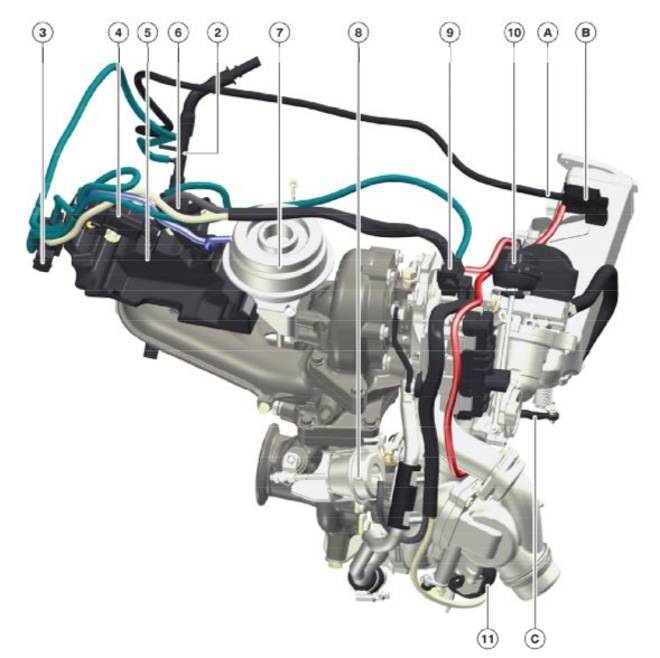
A - Vacuum supply pipeline;
B - EGR bypass flap solenoid valve;
C - Membrane mechanism of the vacuum regulator of the EGR bypass valve;
2 - Vacuum receiver with throttle;
3 - Solenoid switching valve of the bypass damper of the supercharger;
4 - Electro-pneumatic pressure converter for the turbine control damper;
5 - Vacuum receiver;
6 - Electro-pneumatic pressure converter for bypass valve;
7 - Membrane mechanism of the vacuum regulator of the turbine control damper;
8 - Membrane mechanism of the vacuum regulator of the bypass valve;
9 - Solenoid switching valve of the bypass valve of the low pressure stage;
10 - Membrane mechanism of the vacuum regulator of the bypass valve of the low pressure stage;
11 - Membrane mechanism of the vacuum regulator of the bypass damper of the supercharger
Information clippings https://www.drive2.ru/c/2433304/
