Stand for diagnostics of generators and starters MS005. Operating Instructions

AvtoAd
24/08/2023
Contents :
1. Purpose
2. Technical characteristics
3. Complete set
4. Stand description
5. Intended use
5.1. Safety instructions
5.2. Installation and connection of the stand
6. Stand maintenance
6.1. Update of the stand software
6.2. Cleaning and care
7. Main problems and methods of their elimination
8. Disposal
9. Contacts
Introduction
Thank you for choosing TM MSG equipment products.
This Operating Manual contains information on the purpose, configuration, construction, technical characteristics and operating rules of the MS005 stand .
Before using the MS005 stand (hereinafter referred to as the stand), carefully study this operating manual, if necessary, undergo special training at the stand manufacturer.
Due to continuous improvement, the stand design, equipment and software may be subject to changes that are not reflected in this User Manual. The pre-installed software in the stand is subject to updating, in the future its support may be terminated without notice.
1. Purpose
The stand is designed to determine the technical condition of automobile generators with various connection terminals, including generators of the 12V "start-stop" system, starters and 12V lead-acid automobile batteries.
The stand displays the parameters that are measured in real time and outputs them in the form of an oscillogram, which allows you to see a complete picture of the unit's operation and more accurately determine its condition.
Diagnostics of automotive generators and voltage regulators is carried out according to the following criteria:
- - stabilization voltage;
- - operation of the control lamp;
- - FR (Frequency and frequency display of the FR signal, voltage regulator feedback).
- - the size of alternating current pulsations.
For COM generators (voltage regulators):
- - ID;
- - protocol;
- - speed of data exchange;
- - type of LIN protocol;
- - controller self-diagnosis errors.
Diagnostics of car starters is carried out by the nature of changes in voltages and currents at terminals 30, 45 and 50.
2. Technical characteristics
The main ones:
Supply voltage, V - 400
Power network type - Three-phase
Drive power, kW - 7.5
Dimensions (L*W*H), mm - 655×900×1430
Weight, kg - 130
Number of batteries (Not included in the package) - 2 identical 12V lead-acid batteries
Battery capacity - Minimum 45A·h
Automatic charging of battery No. 1 - Yes
Automatic charging of battery No. 2 - Yes
The nominal voltage of the tested units is 12 and 24 V
The maximum overall length of the tested unit, mm (m) - 410 (0.41)
Checking generators:
Load at 12V, A - 300A
Load at 24V, A - 150A
Check mode - Automatic/manual
Load adjustment (0-100%) - Smooth
Turn the drive, rpm - 0-3000
Adjustment of drive revolutions - Smooth
Type of transmission (drive-generator) - V-belt drive/poly-V-drive
Alternator types tested 12V - Lamp, SIG, RLO, RVC, C KOREA, PD, C JAPAN, COM (LIN, BSS), S/A PSA
Tested generator types - 24V - Lamp, COM (LIN)
Checking the starter:
The power of the tested starter, kW - Up to 11
Measurement parameters - Display of graphs showing the start-up mode, changes in voltage and current at the terminals: K30, K50 and K45
Battery check:
Tested battery types - Any 12V lead-acid battery
Measurement parameters - Capacity
Additionally:
Display - Touch 12"
Software Update - Available
Generator Database - Available
Saving diagnostic results - Available
Print - Available
Internet connection - Wi-Fi (802.11a/b/g/ac), Ethernet
Connection of peripheral devices - 2 x USB
3. Complete set
The set of equipment includes:
Stand MSG MS005 - 1pc.
MS33001 – cable with a set of adapter wires for connection to the generator connector - 1pc.
Starter diagnostic cable - 1 pc.
Starter positive terminal adapter - 2 pcs.
MS0114 – fuse (type 22x58mm, current strength 100A) - 1 pc.
Stylus - 1 pc
Wi-Fi module - 1 pc.
Stand door key - 2 pcs.
Socket 400V - 1 pc.
Operating manual (card with QR code) - 1 pc.
4. Stand description
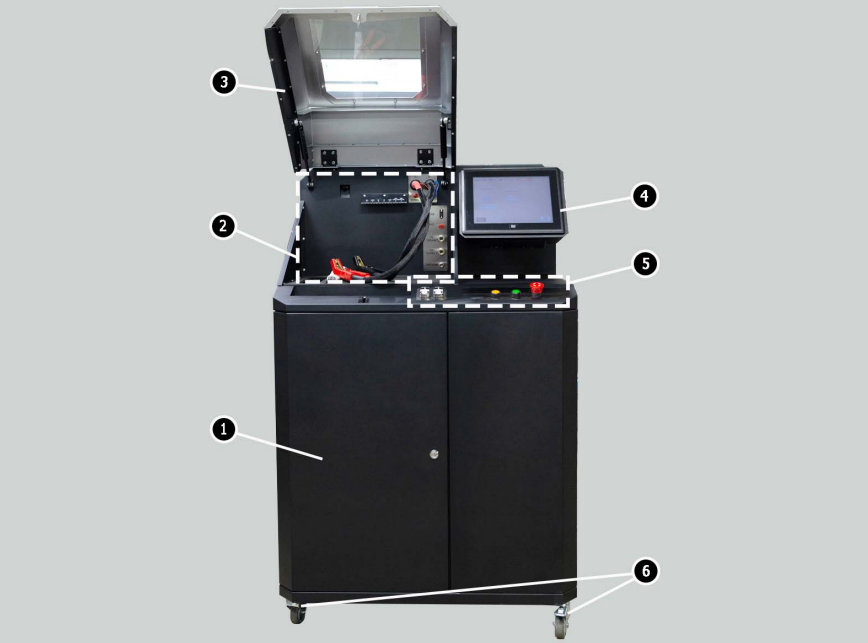
Photo 1. General view of the diagnostic stand
1 – Battery access door.
2 - Work platform.
3 – Protective casing.
4 - Touch screen - for displaying the diagnostic parameters of the unit under test and controlling the functions of the stand.
5 – Control panel.
6 – Swivel wheels with brake.
The work platform (photo 2) contains the following elements:
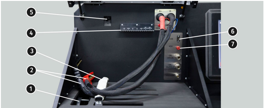
Photo 2. Work area of the stand
1 – Generator drive belts, wedge and poly-wedge.
2 – Power cables "B+" "B-".
3 – Unit fixation chain.
4 – Bracket for diagnostic crocodile cable.
5 – Thermal imaging camera.
6 – Diagnostic cable connector.
7 – Diagnostic cable connection connector for starter diagnostics.
The control panel (photo 3) includes control elements:
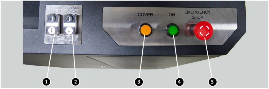
Photo 3. Stand control panel
1 - Control buttons for tensioning and loosening of the generator drive belt.
2 – Control buttons for tightening/loosening the unit’s locking chain.
3 – COVER button – opens the protective cover.
4 - OFF/ON button - responsible for powering the stand. The stand is turned off by pressing the "Turn off the stand" button in the main menu of the service program.
5 – "EMERGENCY STOP" button - emergency stop of the generator drive and chain/belt tightening.
In the lower part of the screen (photo 4) there are: two USB connectors (item 1, photo 4) for connecting computer peripherals (mouse, keyboard, Wi-Fi adapter, printer), as well as one network LAN connector (pos. 2 photo 4).
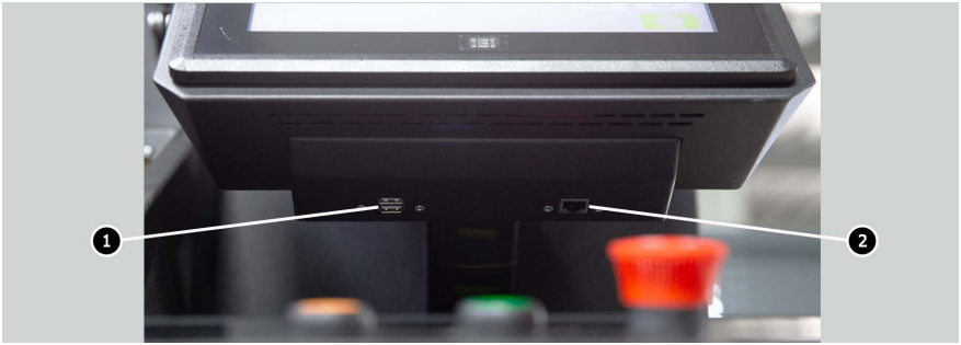
Photo 4. Location of USB and LAN connectors
A diagnostic cable (photo 5) is supplied with the stand, which includes a set of adapter wires (fig. 6) for a more convenient connection to the terminals in the generator connector.
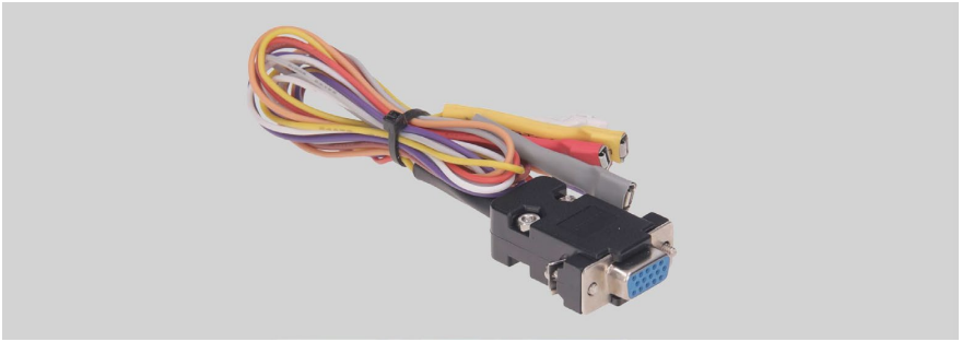
Photo 5. Diagnostic cable MS-33001
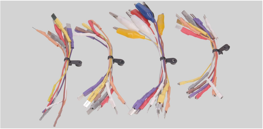
Photo 6. A set of adapter wires
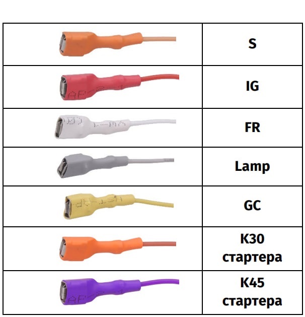
The MS-33001 diagnostic cable has the following color marking of the adapter wires (see also Table 1):
- Orange - " S " (Sense pin) - a terminal that allows you to measure the voltage of the battery with a voltage regulator, as well as compare the voltage of the battery with the output voltage of the generator. Connects to terminal "S".
- Red - " IG " (Ignition) - terminal for connecting the ignition circuit, terminals: 15, A, IG.
- White - " FR " - terminal for transmitting data about the load of the regulator. Connects to terminals: "FR", "DFM", "M".
- Gray - " D+ " - terminal for connecting the control lamp of the voltage regulator. Designed for connection to terminals: D+, L, IL, 61.
- Yellow - " GC " - is used to connect the generator voltage regulator control channel. Connects to terminals: COM, SIG, etc.
- Brown - " K30 " - is connected to terminal 30 of the starter, which is connected to the "+" terminal of the battery.
- Violet - " K45 " - is connected to the output of the starter electromagnet connected to the starter motor.
Table 1 – Color marking of the MS-33001 cable
For ease of use of diagnostic cables, it is recommended to put alligator clips on the bracket.
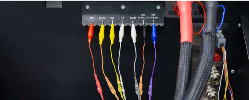
Photo 7. Diagnostic cable clamps fixed on the holder.
When diagnosing the starter, the MS-33001 cable and the cable for connecting terminal 50 are used (photo 8).

Photo 8. Cable for connecting terminal 50 of the starter
5. Intended use
1. Use the stand only for its intended purpose (see section 1) .
2. The stand should be turned off through the interface of the service program by clicking the "Turn off the stand" button.
3. Use the emergency stop button "EMERGENCY STOP" of the stand only if it is necessary to immediately stop the drive of the stand, turn off the tightening of the chain or belt, turn off the supply of power cables.
4. The terminals of the diagnostic cable MS-33001, which are used for diagnosing generators and starters, are connected only to the terminals of the relay-regulator and the terminals of the starter K30 and K45.)
5. To protect the touch screen from damage, use a stylus (included in the kit).
6. In the event of malfunctions of the stand, its further operation should be stopped and the manufacturer or sales representative should be contacted.
The manufacturer is not responsible for any damages or harm to human health due to non-compliance with the requirements of this Operation Manual.
1. Qualified persons who have received the right to work on certain types of stands and have received instruction in safe techniques and operating methods are allowed to work at the stand.
2. The stand must be disconnected from the power supply during its cleaning and cleaning, as well as in emergency situations.
3. The workplace must always be kept clean, well lit and spacious.
4. To ensure electrical and fire safety, IT IS PROHIBITED:
- connect the stand to an electrical network that has faulty protection against current overloads or does not have such protection;
- use a socket without a grounding contact to connect the stand;
- use extension cords to connect the stand to the electrical network. If the outlet is far from the place of installation of the stand, it is necessary to finalize the electrical network and install the outlet;
- operation of the stand in a faulty condition.
- independently repair and make changes to the stand structure, as this can lead to serious damage to the stand and void the right to warranty repair.
5. It is forbidden to leave units with a running drive unattended on the stand.
6. When installing the unit on the stand and removing it, be very careful not to injure your hands.
7. It is forbidden to open the door to access the power part of the stand, if the stand is connected to the 400V network.
5.2. Installation and connection of the stand
The stand is delivered packaged. Free the stand from the packaging materials, remove the protective film from the display (if available). After unpacking, it is necessary to make sure that the stand is intact and there is no damage. If damage is discovered before the stand has been turned on, contact the manufacturer or sales representative
The stand is installed on a flat floor, locking the swivel wheels (minimum two wheels) with the help of a brake mechanism.
The stand remains operational at temperatures from +10°C to +40°C and relative humidity from 10 to 75%.
When installing the stand, keep a minimum space of 0.5 m from the back side of the stand to ensure proper air circulation.
Before starting work on the stand, it is necessary to connect:
- 12V batteries, which must be placed in the battery compartment of the stand (photo 9). Use the keys (included) to open the left door. When connecting the battery, you should follow the markings on the power cables. If you connect only one battery (Battery1 or Battery2), only the 12V diagnostic mode will be available, the 24V mode will not be available.
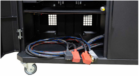
Photo 9. A place for placing batteries in the stand
- 400V electrical network according to the marking inside the socket (supplied in the kit).
6. Stand maintenance
The stand is designed for a long period of operation and does not require special maintenance. However, to ensure the maximum service life, it is necessary to regularly monitor its technical condition, namely:
- checking the operation of the engine (extraneous sounds, vibrations, etc.);
- condition of generator drive belts (visual inspection);
- condition of power lines (visual inspection);
- whether the environment meets the requirements for the operation of the stand (temperature, humidity, etc.).
6.1. Update of the stand software
When connected to the Internet, the stand checks for updates to the software of the diagnostic program, the database and the firmware of the stand. If the stand finds a new version of the software on the company's server, you will be prompted to install the update or ignore it. To start the software update process, press the "OK" button, to refuse - "Skip".
WARNING! The update process may take some time.
WARNING! It is forbidden to turn off the power of the stand to stop the update.
To clean the surface of the stand, you should use soft napkins or rags, as well as neutral detergents. The display should be cleaned using a special fiber cloth and spray for cleaning monitor screens. To avoid corrosion, failure or damage to the stand, do not use abrasive materials or solvents.
7. Main malfunctions and methods of their elimination
1. The stand does not start
- The automatic switch behind the left door of the stand is activated - open the left door with the key from the set, turn the automatic switch to the upper position
- Left door open, left door safety limit switch tripped - close left door
- One of the stand power phases (L1/L2/L3) or neutral N is missing - restore power
2. The stand works, but the electric motor does not start
- Variable speed drive software error - contact your sales representative
- The electrical wiring of the stand is damaged - contact your sales representative
3. Extraneous sounds are heard during the operation of the stand
- Unit under test installed incorrectly (Drive belt stretched or misaligned) - reinstall the unit under test
4. During the operation of the stand, the belt slips (whistles)
- Insufficient belt tension - stop the drive and check the belt tension
- Belt wear - replace the belt
5. When checking the generator, the contact clamps ("crocodiles") get very hot
- Small contact area - use an adapter for the positive terminal of the generator
8. Disposal
When disposing of the stand, the European directive 2202/96/EC (WEEE Directive - Directive on waste electrical and electronic equipment) applies.
Obsolete electronic devices and electrical appliances, including cables and fittings, as well as batteries and rechargeable batteries, should be disposed of separately from household waste.
To dispose of waste, use the return and collection systems you have at your disposal.
Proper disposal of old appliances helps prevent damage to the environment and health.
HEAD OFFICE AND PRODUCTION
St. Biological, 18,
61030, Kharkiv
Ukraine
+38 057 728 49 64
+38 063 745 19 68
E-mail: sales@servicems.eu
Website: servicems.eu
REPRESENTATIVE OFFICE IN POLAND
STS Sp. z o. o
St. Modlinska 209,
03-120 Warsaw
+48 833 13 19 70
+48 886 89 30 56
E-mail: sales@servicems.eu
Website: msgequipment.pl
TECHNICAL SUPPORT SERVICE
+38 067 434 42 94
Email: support@servicems.eu