NOx sensor

AvtoAd
10/02/2023
Content
1. Principle of action.
2. User manual.
3. Troubleshooting.
4. Warranty.
The new NOx sensor provides precise urea dosing and can directly replace the OE sensor.
A NOx (nitrogen oxide) sensor is usually a high-temperature device that
measures the level of oxides in exhaust systems, which is strictly regulated by authorities in all parts of the world. The measurement also helps to optimize engine performance by ensuring proper functioning of the exhaust gas aftertreatment system.
All NOx sensor products meet OE criteria and are calibrated and monitored in testing facilities. Available spare parts for DAF, Iveco, MAN, Mercedes-Benz, Renault, Scania and Volvo. All products have a 1-year warranty.
The principle of action
The NOx sensor works like an oxygen sensor with enhanced functionality. The sensitive element is a ceramic chip (see Figure 1), which consists of a heating circuit, a small passage leading to two cavities, an oxygen pumping circuit and a NOx decomposition circuit.
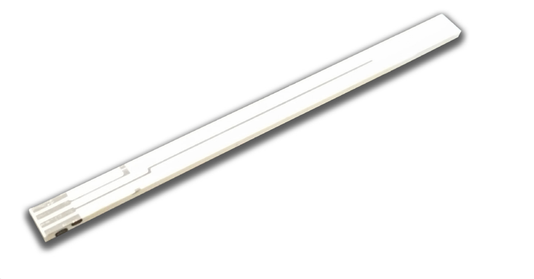
NOx sensitive element in longitudinal section:
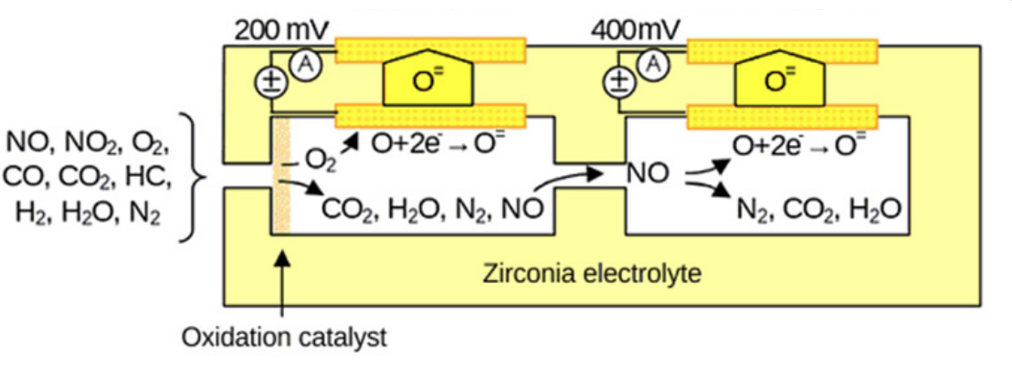
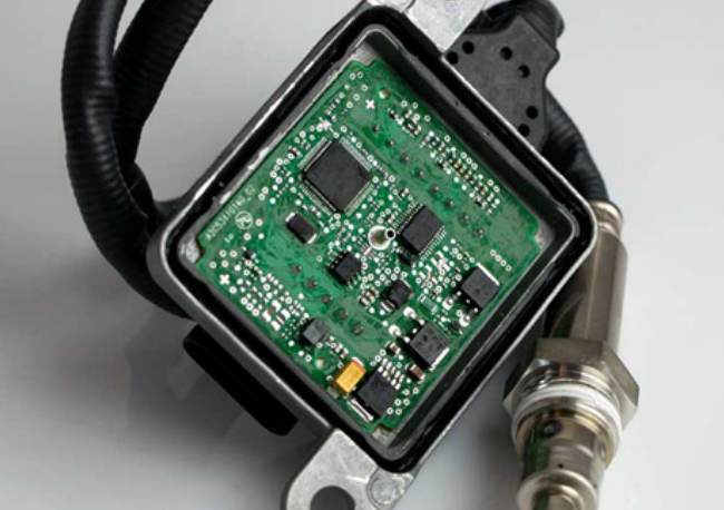
Before work, the ceramic chip is heated for about 1.5 minutes. When the exhaust gas enters the ceramic chip through a small passage (see Fig. 2), in the first cavity all free oxygen molecules are pumped through the electrolyte, and the remaining gases diffuse into the second cavity, where the NOx molecules decompose and oxygen is formed. measured as a small electric current. An additional board (see Fig. 3) is used to convert the measured current into a signal compatible with the engine control unit (ECU) communication protocol.
user manual
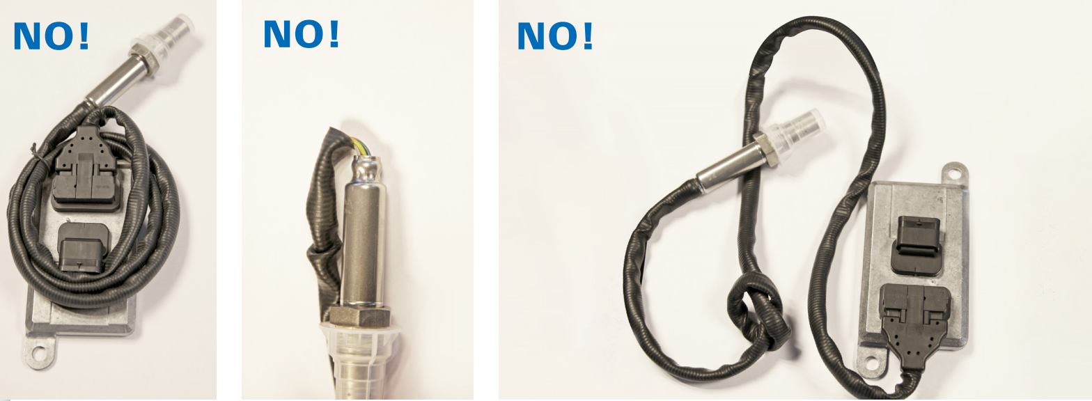
The supply voltage of Dinex NOx sensors is limited to 9 – 36 Volts, and the signal voltage is 2.5 to 3.6 Volts. It is strictly forbidden to change the location of the connecting wires. When storing or installing, make sure the sensor wires hang without tension. When properly installed, the sensor wire should make a 180 degree loop to provide a safe distance (see Figure 4). It is also forbidden to wind or bend the wire (see Fig. 5).

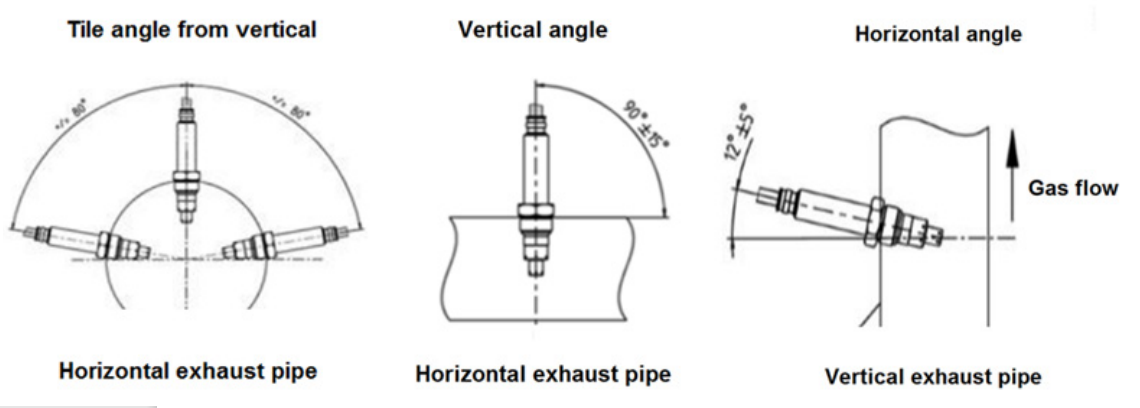
When installing a NOx sensor in non-specific (new) applications, please carefully consider the location of the sensors. It should not be placed too close to bends, as turbulence will disrupt proper operation. The installation angle should be vertical, at a considerable distance from any bends (see Fig. 6).
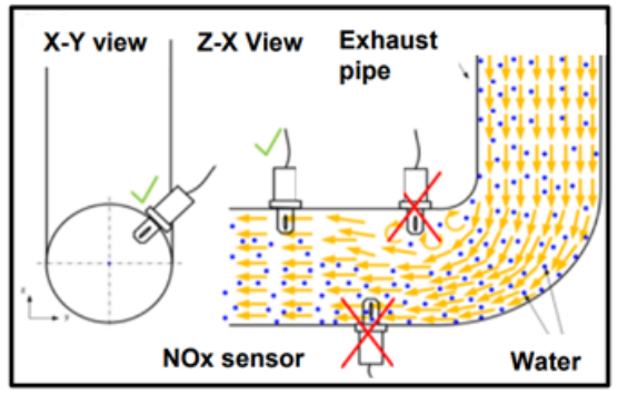
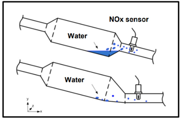
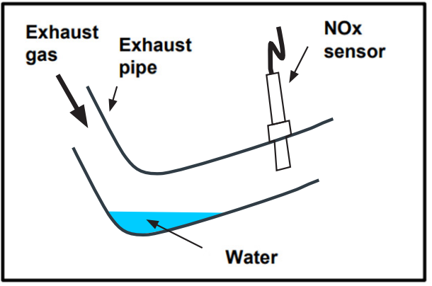
When choosing the location of the NOx sensor, please also consider the possibility of water condensation in the exhaust system. Some examples of this problem are shown in figures 8 and 9. The position of the sensor should be chosen in such a way that there is no risk of condensation coming into contact with the sensor head during operation. Additional placement suggestions are provided in Figure 7.
When replacing the NOx sensor, pay attention to its designation. Sensors that are located in front of the catalytic converter are considered "upstream" and those that are located after the catalytic converter are considered "downstream". The NOx concentration at both of these locations is very different, so some applications may use different sensors for the upstream and downstream locations. It is very important to avoid any confusion. Please handle the product with care, do not use any sprays or chemicals for cleaning or painting, do not attempt to wash the sensor and its components with water or disassemble them. Using such methods creates a serious risk of failure (see Fig. 10).

Troubleshooting
Before replacing your old NOx sensor, it's important to understand why it failed. The following are possible causes of failures.
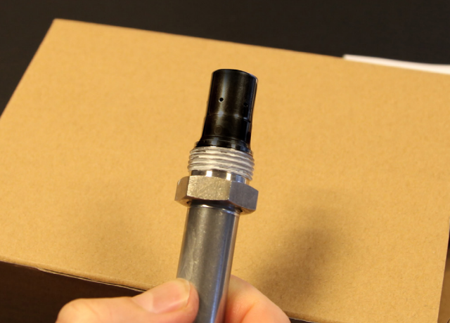
• Excessive soot/ash content in exhaust gases. The sensor head will be black (see Figure 9).
• Contaminated exhaust gases. Engine oil contamination is a common problem that indicates engine wear
components.
• No or excessive supply voltage due to short circuit, sudden power surges or external power source.
• Direct contact with condensate during operation.
It is important to correct any of the above problems before installing a new NOx sensor, otherwise the risk of re-damage remains. If the newly installed sensor is not recognized or does not work, please use a multimeter to check that the power supply is within 9-36V (12V nominal) at the sensor connector. Also, make sure you follow all NOx sensor replacement instructions provided by your vehicle manufacturer. If the sensor connects and is recognized but shows signs of abnormal operation, please make sure the correct sensor is selected for its location.
Guarantee
Before installing a Dinex product, make sure that all problems in the troubleshooting section have been resolved. If the warranty inspection shows evidence of any of the problems listed in the troubleshooting section, the claim will be rejected. Also, for the warranty to be valid, the sensor housing and wiring must show no visible signs of damage. If the sensor thread or nut is damaged, this indicates excessive force, which can potentially lead to failure (see Figure 11).
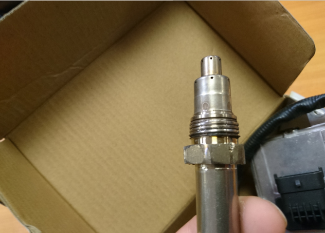
If there are significant soot/ash spots on the sensor head (see Figure 12), this indicates a damaged DPF or a poorly calibrated engine. The sensor chip is easily damaged in this case, so the warranty is lost.
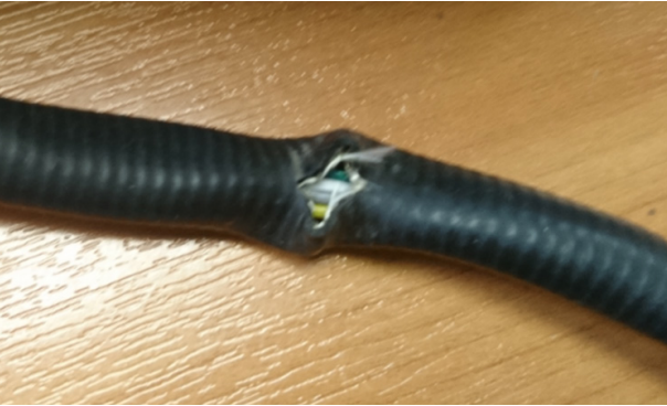
Damaged wire protection indicates improper handling (see Figure 13), which may damage the wiring. In order for the warranty to be valid, there should be no signs of damage to the wire.
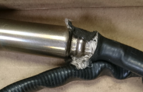
The area where the wiring connects to the sensor head is the most critical and prone to loss of communication if handled improperly (see Figure 14). In case of damage, the warranty does not apply.
Do not attempt to wash or submerge the sensor. Do not use any sprays. Store only in a dry environment. If traces of water are found in the sensor head or any chemical traces on the product, the warranty will be void.