MK7.5 OEM LED Headlights Retrofit

AvtoAd
05/11/2021
I purchased my 2019 GTI last March. I was super excited to upgrade from a Jetta but in the process, I overlooked a few things. The biggest blunder was not getting the lighting package. Since my daily commute is long and I’ve almost hit a few deer in the morning due to low visibility. I felt upgrading the halogen lights was a worthy investment.
Update:
18-Aug-2021
While helping someone out on their retrofit, I notice what I believe are errors on the 14 Pin connector information. Made the corrections and added the actual light diagram. I need to validate if pin 13 on both light go to T73a/72, looks that way from the diagram.
30-May-2021
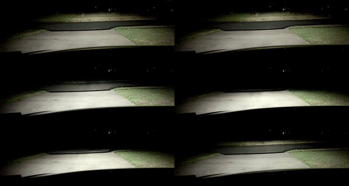
The following diagram shows the different light modes available. While coding DLA on a friends car, I started to question why I have the different modes enable. Ended up logging the light distribution output to figure out what speeds trigger the different modes. I found that you have to maintain the speed at the different ranges for the lights to change to the different modes.
- Junction Light - Enable with dynamic cornering, also works with turning with fog
- City Light - Patterned enable on speeds less than 20 MPH or when turning
- Country Lights - Default light pattern
- Motorway Light (Highway light) - Patterned enable on speeds greater than 70 MPH
- Updated module 4B Coding to fix errors, added City Lights, Highway lights, and High Beam Assist
- Updated module 09 to include High Beam Assist
- Added coding for module A5 and High Beam Assist
- Added Light Assist settings
Things to know
- This is a Next Level Retrofit that requires money, time, plenty of patience, and at times prayer
- Disconnect your battery before messing with anything electrical
- I’m not responsible if you screw up your car
- I am open to answering any questions to the best of my ability
- The LED lights are sort of non-serviceable, so the housing already has the bulb
- There are 3 versions of the LED lights, 8IT, 8IU, 8IX (US version with amber reflector are based on this model)
- Only the 8IU is capable of full dynamic light assist (dual beams that dynamically adjust)
- The lights require two modules. One controls the power and the other the vertical/horizontal axis
- The modules have firmware specific to the type of light they are being used on (in case you source your parts second hand like I did)
- One headlight was sourced from someone that said it was new but never installed. It had the proper modules attached. I'm no sure if new lights ship this way so please confirm.
- The light modules are program by the 4B module. So, if you did like me and got a used module coded for the wrong vehicle (or a virgin one) it needs the proper firmware and parameters loaded to actually work
- Parameters/firmware can only be loaded by VCP or ODIS
- The official wiring diagram is garbage and the engineer who did it should be fired
- Someone posted a link on the vortex “Shop manuals for MK7.5,” this manual is better than the one in the erwin.vw.com site which requires paid access
VAG Parts list
- 5q0937085bs - 09 If needed. BCM Restyling unit
- 3Q0907338C – 4B Multifunction module
- 8W0972420A - 4B Multifunction module wire terminal
- 7P5941572A - Main Power LED Module (1 for each light)
- 8V0907399D - LED Control Unit Module (1 for each light)
- N10708601 - Screws for the modules (I got some from Lowes that have the same thread and cut them to size)
- 5Q0512521J - Level Adjust Sensor (not needed if you have DCC)
- M5 bolts/washer/locking nuts - I think I went with 12mm bolt length
- 5GM941077A [5GM941059A - old] – GTI US - Left LED Headlight
- 5GM941078A [5GM941060A – old] – GTI US - Right LED Headlight
- Wire harness – got it from AliExpress, I didn’t see one that was exactly for the LED lights so you will need to massacre this one to make it work. PAY for the faster shipping!
- FOR VW Golf 7 MK7 Xenon Headlight Auto Leveling Range Headlight Cornering AFS Wire/cable/Harness Xenon Lamp LED Light
- https://www.aliexpress.com/item/32974089857.html?spm=a2g0s.9042311.0.0.3bba4c4dfM036j
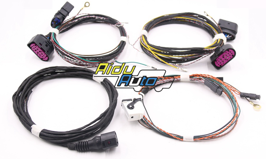
Special tools/parts
- Terminal removal tool set – needed to re-pin the cables
- Body panel tools – makes taking panels off easy
- Soldering iron/solder
- Heat shrink assorted set – to properly protect splices (I started with electrical tape but this is better)
- Tesa Tape 51036 – to wrap your engine wires (one roll should be enough)
- Tesa Tape 51608 – to wrap your in-cabin wires (one roll should be enough)
- Torx bit set – I think T40 and T30 are the ones I used but get a set if you don’t have one
- 5 AMP mini fuse – for the headlights (1 per light)
- VAG Connector Removal Tool – makes taking the headlight plugs off easier
- OBDeleven/VCDS/VCP/ODIS – to reprogram module 9, 19, and 4B
- VCP – if you source parts from ebay from random cars like I did, you will need VCP to load the proper firmware and parameters (apparently ODIS can do this)
- Screw drivers/sockets/scissors/a good playlist

 or that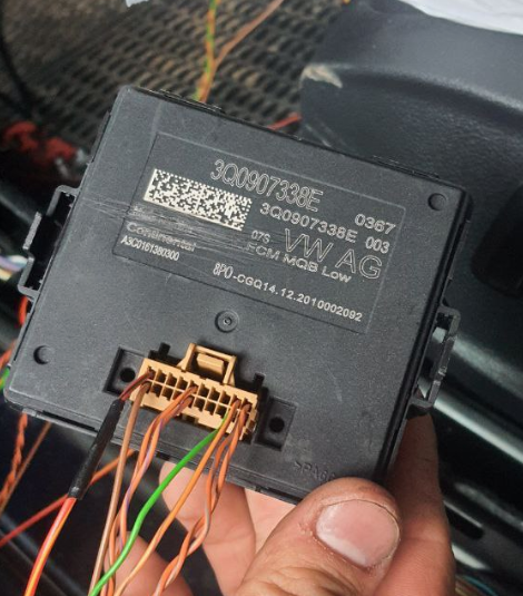
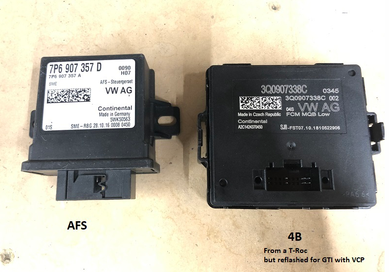
MK7 AFS and MK7.5 4B module
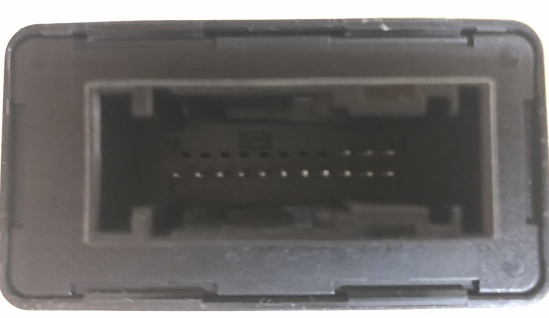
MK7 AFS connector, supposed to be a 26 Pin connector but it only uses 22
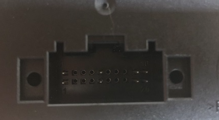
MK7.5 4B connector
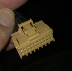
MK7.5 4B terminal
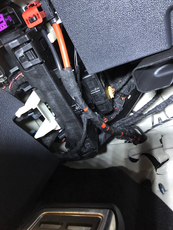
Installing the rear left level sensor should be easy enough if you purchased the harness. You will need to remove the back seat and the door sill panel. One of the challenges is to get the sensor to sit the proper way. The other is splicing pin 3 of the sensor to the existing wire on T73a/22, my GTI already had something there.
Install the sensor on the rear left side.

Before running the harness, I put it in a flex wire conduit and warp it with tape for protection.
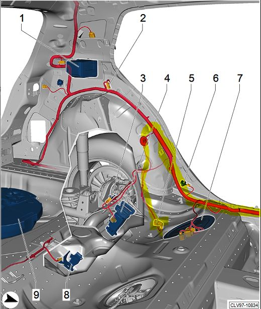
I found that running the harness on the top side of the subframe to be the best way. I couldn’t get a good picture but you should understand once you run the harness.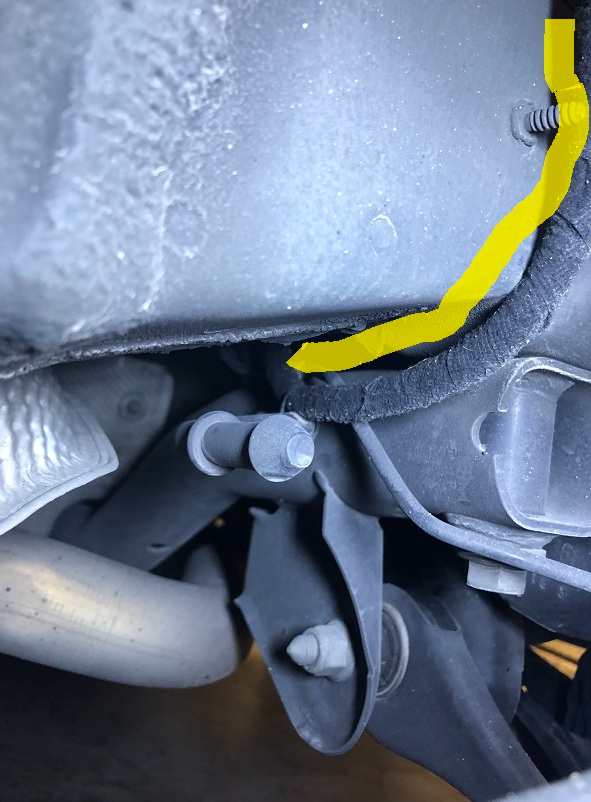
Remove the wheel well cover if you haven't done so yet. Cut into the grommet to get inside the cabin, don’t forget to seal this afterwards, I used a hot glue gun.
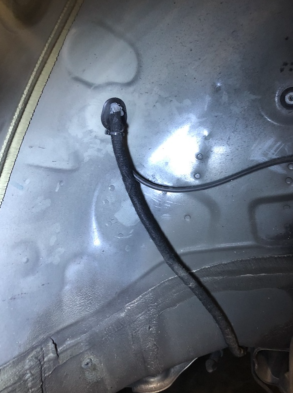
Once there, follow the rest of the wires to the front of the car to the BCM.
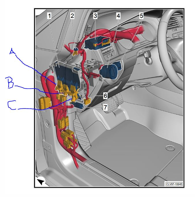
Once you get the harness to the front, remove the hood handle and the panel behind it to access the BCM harness. Connect the cables using the following table.
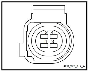
4-pin connector - T4az
1-Signal
2-
3- Power +5V
4- Ground -5V
| Pin | Wire Color | BCM |
|
1 |
Blue | T73a/23 |
|
3 |
Black | T73a/22 |
|
4 |
Brown/Red | T73c/57 |
At this point I’m really hopping you are committed. This is the point of no return and it will take some time to put the GTI (or whatever type of V-Dub you have) together again. This is the point where I lost my mind due to not knowing what I do now about this retrofit. It will take at least a day if doing it by yourself so plan accordingly.
The high level overview is: remove the battery, run wire harness, re-pin the new 14-pin connector, verify wire with multi meter, and the install headlights. I’ll put the connection info on the 4B installation post.
The first thing to do is remove the battery.
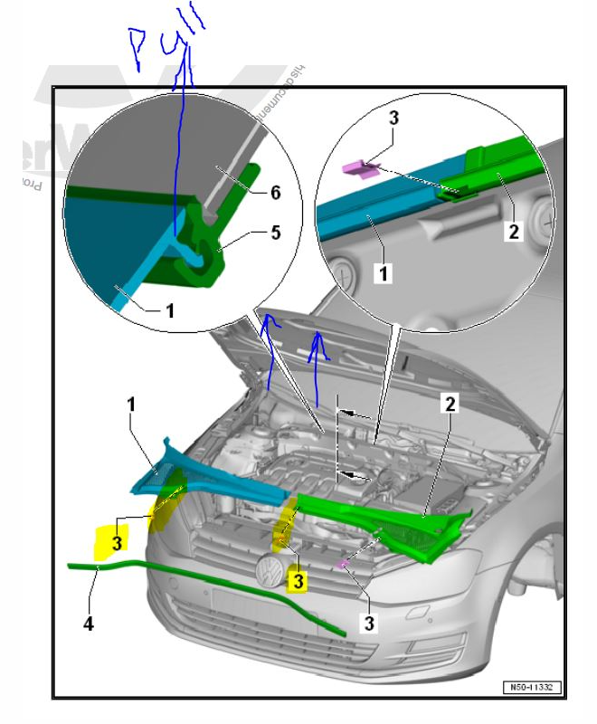
Remove the rubber strip from the plenum chamber cover. Then remove the two clips (3) holding the left side. Pull straight up on the cover to remove it from retainer (5).
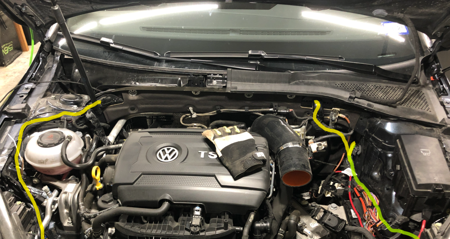
Run the right headlight hardness following the yellow path. Run the left headlight hardness following the green path.
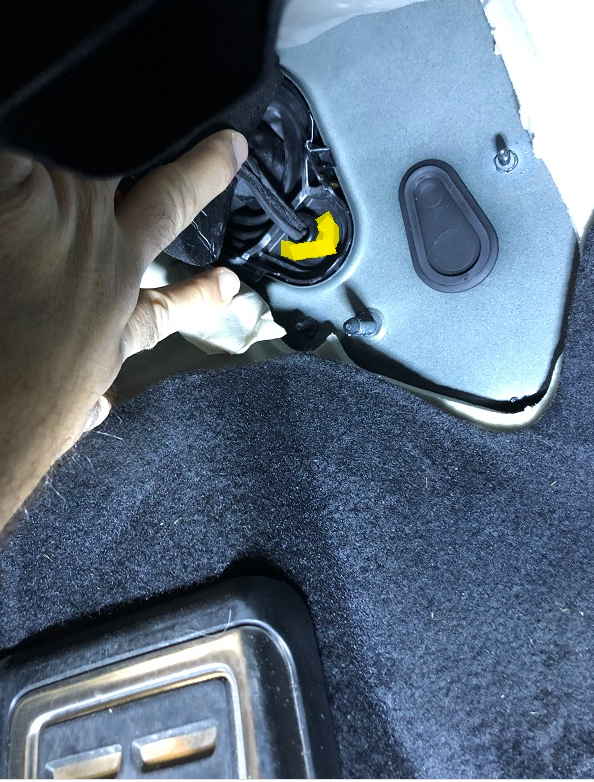
From the inside of the cabin, puncture a hole on the yellow part of this grommet to run the wire harness inside. I found a wire cloths hanger super helpful in this step.
Re-Pin the original 10 pin Halogen lights connector to the 14 pin LED lights connector. For the wires that are not used, cut them and put black tape or a shrink wrap sleeve on the tips. Then wrap them around the harness. Use some tape to wrap them to the harness. I cut and solder some of the wires since some of the pins in the 14 pin connector are smaller than the 10 pin connector. This is why checking the wires with the multi meter is extremely important. When putting the pins in the connector, try to reuse the rubber gasket to stop humidity/water from getting to the terminals.
| Left | |||||||
| 10-Pin connector | Wire Color | 14-Pin connector | Wire Color | Function | BCM connection | 4B connection | Note |
| 1 | Orange/Gray | CAN-H | 15 | ||||
| 2 | Orange/Brown | CAN-L | 5 | ||||
| 4 | 12v | Splice to 8 |
|||||
| 5 | Brown | GND | Use the ground by the driver side door | ||||
| 6 | Yellow | 6 | Yellow | Signal | 73c/5 | ||
| 7 | GND | Splice to 5, |
|||||
| 8 | Black/Lilac | 12v | New Fuse 37 | ||||
| 8 | White/Black | 11 | Blue/White | Signal | 46b/39 | ||
| 1 | Black/White | 13 | Gray/Black | Signal | 73a/72 |
| Right | |||||||
| 10-Pin connector | Wire Color | 14-Pin connector | Wire Color | Function | BCM connection | 4B connection | Note |
| 1 | Orange/Gray | CAN-H | 15 | ||||
| 2 | Orange/Brown | CAN-L | 5 | ||||
| 4 | 12v | Splice to 8, |
|||||
| 5 | Brown | GND | Use the ground by the driver side door | ||||
| 6 | Yellow/Blue | 6 | Yellow/Blue | Signal | 46b/1 | ||
| 7 | GND | Splice to 5, |
|||||
| 8 | Gray/Black | 12v | New Fuse 36 | ||||
| 8 | White/Purple | 11 | Blue/White | Signal | 46b/2 | ||
| 1 | Gray/Black | 13 | Gray/Black | Signal | 73a/72??? |
Wiring diagram
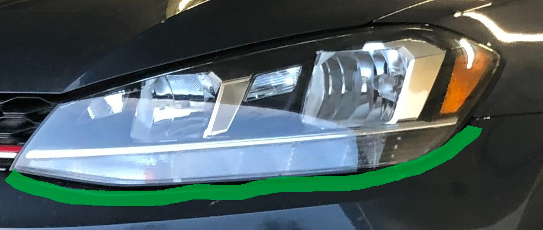
Before removing the headlights, use tape to outline how they fit on the bumper. This helps in making the new headlights flushed.
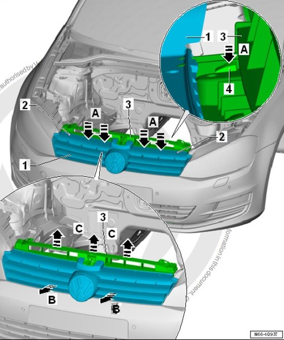
Remove the two screws holding the grill in and pull the grill off. Point to think about, this will remove the radar from the car. However, since no real change has been made to the cars dimension, it should still be within specs after re-installation. Remove the radar plug.
*Since completing this guide, I have retrofitted the front assist camera. I can confirm that if the radar is removed while the battery is disconnected, there should be no issues with the radar if re-installed properly.
Remove the screws inside the wheel well.
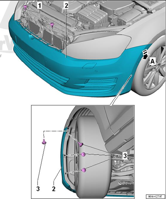
Remove the screw behind the bumper holding the light.
Remove the bolts holding the headlight in place to include the metal bar.
I remember some screw/bolts I loosen up after removing the grill that allow me to pull on the bumper more so I can slide the headlights out.

Finally install the new lights and reverse the process to put everything back in place.
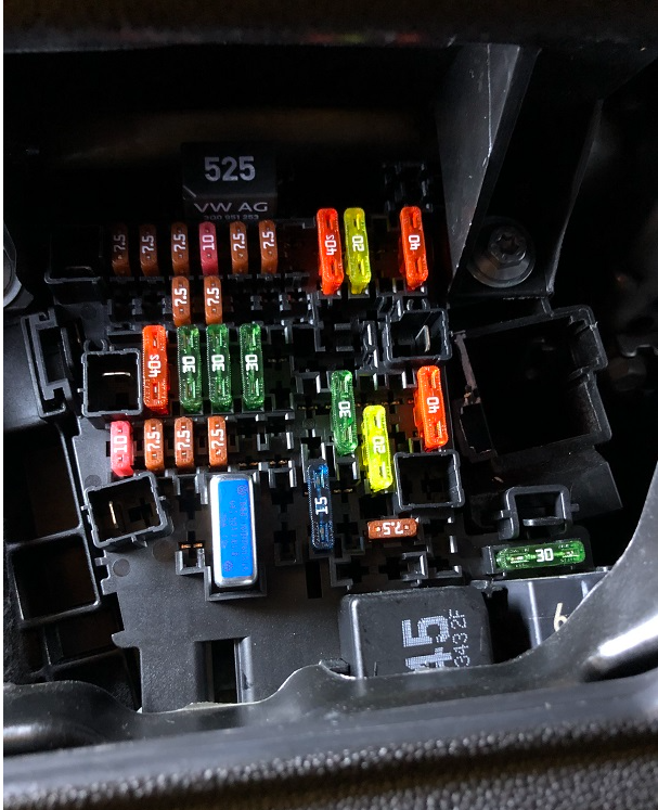
I went the extra mile to get my fuse box to look OEM. It was an extremely difficult process as there is almost no room to work with. Removing the dead pedal (I have a DSG) help give me a bit more room but it’s a pain to get off and you might break a clip. Here is a before fuse box just for reference.
I took a bunch of stuff off but I think just removing the three bolts (yellow arrows) will allow enough play to get the fuse carrier to move forward. There are three clips (green arrows) holding it in place before it actually moves.
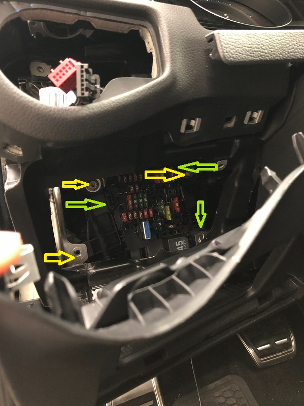
You should be able to push it from the back and stick a panel tool or screw driver on the left side to hold it in place. The following picture is the back of the fuse carrier. The goal is to move the fuse carrier forward enough that you can move the purple looking plastic lock lever past the lip. Do not try to move the lock if you cannot see it from the front, it will just break. I had this happen to the top one.
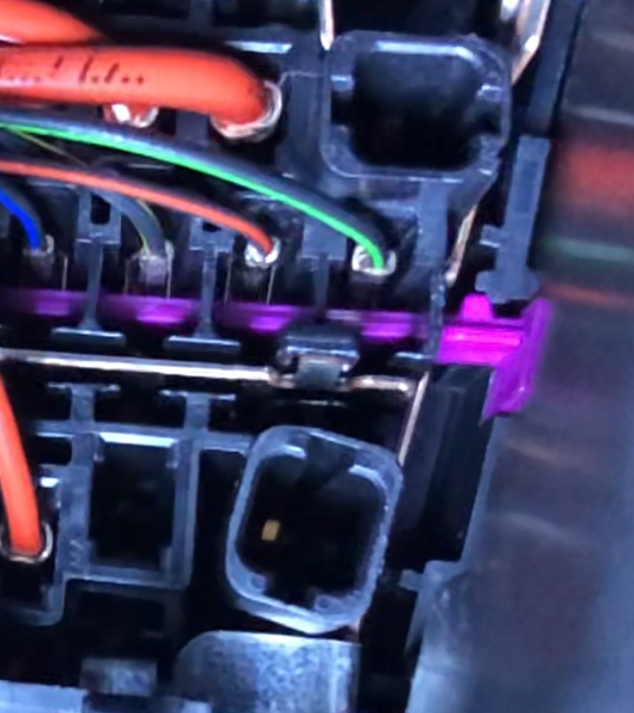
Once the fuse lock is open, you should be able to slide in the cables for fuse 36 (right headlight) and 37 (left headlight). I found that sticking in a zip tie from the front help me find my place.
I’m assuming you went with the wire harness. You will finish butchering it in this step to make it do what is required to finish the wiring. You need to connect the 4B module into Gateway module. The best way is to create a new hardness out of the harness that should have gone to the AFS unit on the MK7. This absolutely works with everything you have. The blue plug will be used as the junction for the cables already connected to the gateway. Hopefully the following diagram makes enough sense to build this.
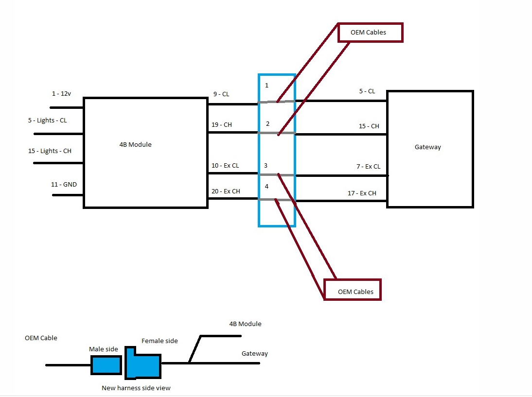
Basically, you are making a Y-cable. The blue connector will accept the OEM cables that were originally going to the Gateway’s Pins 5, 15, 7, and 17. On the other side, you will splice cables that will connect to the Gateway and the 4B module, creating that Y. Don't forget to double check your work with a multi meter.
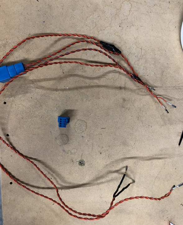
All ground cables will go to the ground by the hood latch handle.
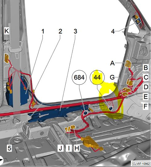
The 12v will need to be connected to a source that receives power from terminal 30. The fuses for this are impossible to reach so I went with the light switch Pin 8 (Red and white cable). If you go this route, the power cable can be pushed toward the front of the car and will drop right by where I recommend you install the 4B module.

Lastly, I found that using a piece of Velcro tape was the best way to secure the 4B module behind the BCM.
Prerequisites
- Left Headlight - 29
- Software: 8V0907399D
- Version 0014
- Left Headlight - 39
- Software: 8V0907399D
- Version 0014
- Multifunction Module - 4B
- Software: 3Q0907338C
- Version 0346 (stock firmware 0286 works, not to be confused by the Skoda version 0286)
- Light Control Left 2 – D6
- Software 7P5941572A
- Version 0002
- Light Control Right 2 – D7
- Software 7P5941572A
- Version 0002
Module 4B should be auto detected and OBDEleven should ask you to code the newly discover module. If you choose to not let it code it just do the following.
Control unit: 19 Gateway
Code:
    Adaptions:

    Installation list, specified installations
        Multifunction Module: [there are two entires; one at after Node_0x08 and the other after Node_0xA8]
            coded

    Long coding:

        FPA_Fuktion_AFS:
            active
Control unit: 4B Multifunction Module
Code:
    Long coding:
        000000050900194A01101F60220000000000000000000000000000000000

        lcm_afs_leimo_mounted:
            Automatic high beam assist
        LED_Headlight:
            enabled
        Function_activation_AFS:
            activated
        Vehicle type:
            19 (not sure what the possibilities are but this is the one most golf are set to)
        Rain/light sensor:
            installed
        Left-/right hand driving switch-over:
            Right hand driv.
        chassis_unit:
            Mehrlenkerhinterachse Frontantrieb
        disable_afs:
            AFS III Abschaltung MFA+
        Start-stop:
            Supported (if you actually have it)
        steering_curve:
            mqb_direct_steering
        lwr_sensor:
            1_sensor (if you are like me and don't have DCC)
        Source_height_value:
            BCM (again, if you don't have DCC)
        market:
            ece (I'm in the USA but this makes the light more dynamic)
        headlamp_coding_word:
            1
        Headlight Regulation:
            enable (Enabling this makes the lights bend more)
        Dynamic AFS light:
            enable
        City light:
            enabled (if enabled, it changes the light patterned to City Lights)
        Highway light:
            enabled (if enabled, it changes the light patterned to Motorway Lights)
        rain_light:
            enabled
        All-weather lights:
            not enabled
        mdf_activation:
            not enabled (this is part of Dynamic Light Assists)
        glw_activation:
            not enabled (part of Dynamic Light Assists)
        glw_with_lwr_activation:
            not enabled (previously enabled, part of Dynamic Light Assists)
        High Beam Assistance:
            enabled (if you actually have module A5 installed, not compatible with DLA)
        Static AFS light:
            ECER R119 (corner lights come on once you engage the turn signal and you slow down)
        Eco mode:
            not enabled (keeps the lights moving dynamically in eco mode)
        Dynamical_Low_Beam_Light:
            enabled (not sure if it makes a difference)
        segmented_cornering_light:
            enabled (not sure if it makes a difference)
        motor_variant:
            Combustion engine
        Funtion_activation_RTM
            active
        multi_function_camera:
            installed (was giving me issues when not enabled, even if you don't have the camera)
        highway_light:
            not enabled (previously enabled)
        race_light:
            not enabled (previously enabled)


    Adaptations:
        Presentation run dynamic AFS light:
            ---:
                active
        Adaptive light functions:
            ---:
                active
        Reference_Run_Start_Condition:
            ---:
                Engine start
        Installation list, specified installations:
            Multifunction Module:
                Yes
            Multifunction module on the second bus connection:
                Yes
            Light Control Left:
                Yes
            Light Control Right:
                Yes
            Light Control Left 2:
                Yes
            Light Control Right 2:
                Yes
            Antenna Control Module:
                No
            Telematics Communication Unit:
                No
When 4B is coded, clear all errors on 29, 39, D6, and D7. Clear errors on 4B, headlight basic settings should still be an error.
Perform headlight basic settings:
- Basic settings
- Basic headlight settings
- Activate
- Basic headlight settings
- Back to Basic settings
- Acknowledge basic settings
- Activate
- Acknowledge basic settings
- verify coding
- verify adaptions
- reset the module
- clear faults
- perform basic settings again
Control unit: 09 Central Electrics
Code:
    Adaptations:

############################ Disable old light settigns ############################
        Leuchte 0 BLK VL B36:
            Lasttyp 0:
                not active
            Lampendefektbit Position 0:
                0
            Fehlerort mittleres Byte DTC-DFCC 0:
                0
            Lichtfunktion A 0:
                nicht aktiv
            Lichtfunktion B 0:
                nicht aktiv
            Dimmwert AB 0:
                0
            Lichtansteuerung HD AB 0:
                always
            Lichtfunktion C 0:
                nicht aktiv
            Lichtfunktion D 0:
                nicht aktiv
            Dimmwert CD 0:
                0
            Dimming Direction CD 0:
                maximize
            Lichtfunktion E 0:
                nicht aktiv
            Lichtfunktion F 0:
                nicht aktiv
            Dimmwert EF 0:
                0
            Dimming Direction EF 0:
                maximize
            Lichtfunktion H 0:
                nicht aktiv
            Dimmwert GH 0:
                0
            Dimming Direction GH 0:
                maximize
            Lichtfunktion G 0:
                nicht aktiv
        Leuchte1BLK VRB20:
            Lasttyp 1:
                not active
            Lampendefektbitposition 1:
                0
            Fehlerort mittleres Byte DTC-DFCC 1:
                0
            Lichtfunktion A 1:
                nicht aktiv
            Lichtfunktion B 1:
                nicht aktiv
            Dimmwert AB 1:
                0
            Lichtansteuerung HD AB 1:
                always
            Lichtfunktion C 1:
                nicht aktiv
            Lichtfunktion D 1:
                nicht aktiv
            Dimmwert CD 1:
                0
            Dimming Direction CD 1:
                maximize
            Lichtfunktion E 1:
                nicht aktiv
            Lichtfunktion F 1:
                nicht aktiv
            Dimmwert EF 1:
                0
            Dimming Direction EF 1:
                maximize
            Lichtfunktion G 1:
                nicht aktiv
            Lichtfunktion H 1:
                nicht aktiv
            Dimmwert GH 1:
                0
            Dimming Direction GH 1:
                maximize
        Leuchte2SL VLB10:
            Lasttyp 2:
                not active
            Lampendefektbitposition 2:
                0
            Fehlerort mittleres Byte DTC-DFCC 2:
                0
            Lichtfunktion A 2:
                nicht aktiv
            Lichtfunktion B 2:
                nicht aktiv
            Dimmwert AB 2:
                100
            Lichtansteuerung HD AB 2:
                always
            Lichtfunktion C 2:
                nicht aktiv
            Lichtfunktion D 2:
                nicht aktiv
            Dimmwert CD 2:
                0
            Dimming Direction CD 2:
                maximize
            Lichtfunktion E 2:
                nicht aktiv
            Lichtfunktion F 2:
                nicht aktiv
            Dimmwert EF 2:
                0
            Dimming Direction EF 2:
                maximize
            Lichtfunktion G 2:
                nicht aktiv
            Lichtfunktion H 2:
                nicht aktiv
            Dimmwert GH 2:
                0
            Dimming Direction GH 2:
                maximize
        Leuchte3SL VRB21:
            Lasttyp 3:
                not active
            Lampendefektbitposition 3:
                0
            Fehlerort mittleres Byte DTC-DFCC 3:
                0
            Lichtfunktion A 3:
                nicht aktiv
            Lichtfunktion B 3:
                nicht aktiv
            Dimmwert AB 3:
                0
            Lichtansteuerung HD AB 3:
                always
            Lichtfunktion C 3:
                nicht aktiv
            Lichtfunktion D 3:
                nicht aktiv
            Dimmwert CD 3:
                0
            Dimming Direction CD 3:
                minimize
            Lichtfunktion E 3:
                nicht aktiv
            Lichtfunktion F 3:
                nicht aktiv
            Dimmwert EF 3:
                0
            Dimming Direction EF 3:
                maximize
            Lichtfunktion G 3:
                nicht aktiv
            Lichtfunktion H 3:
                nicht aktiv
            Dimmwert GH 3:
                0
            Dimming Direction GH 3:
                maximize
        Leuchte4TFL LB4:
            Lasttyp 4:
                not active
            Lampendefektbitposition 4:
                3a
            Fehlerort mittleres Byte DTC-DFCC 4:
                49
            Lichtfunktion A 4:
                Tagfahrlicht
            Lichtfunktion B 4:
                nicht aktiv
            Dimmwert AB 4:
                127
            Lichtansteuerung HD AB 4:
                always
            Lichtfunktion C 4:
                Blinken links aktiv (beide Phasen)
            Lichtfunktion D 4:
                nicht aktiv
            Dimmwert CD 4:
                0
            Dimming Direction CD 4:
                minimize
            Lichtfunktion E 4:
                Standlicht allgemein (Schlusslicht, Positionslicht, Begrenzungslicht)
            Lichtfunktion F 4:
                Parklicht links (beidseitiges Parklicht aktiviert li & re)
            Dimmwert EF 4:
                127
            Dimming Direction EF 4:
                maximize
            Lichtfunktion G 4:
                nicht aktiv
            Lichtfunktion H 4:
                nicht aktiv
            Dimmwert GH 4:
                0
            Dimming Direction GH 4:
                maximize
        Leuchte5 TFL RB32:
            Lasttyp 5:
                not active
            Lampendefektbitposition 5:
                44
            Fehlerort mittleres Byte DTC-DFCC 5:
                4b
            Lichtfunktion A 5:
                Tagfahrlicht
            Lichtfunktion B 5:
                nicht aktiv
            Dimmwert AB 5:
                127
            Lichtansteuerung HD AB 5:
                always
            Lichtfunktion C 5:
                Blinken rechts aktiv (beide Phasen)
            Lichtfunktion D 5:
                nicht aktiv
            Dimmwert CD 5:
                0
            Dimming Direction CD 5:
                minimize
            Lichtfunktion E 5:
                Standlicht allgemein (Schlusslicht, Positionslicht, Begrenzungslicht)
            Lichtfunktion F 5:
                Parklicht rechts
            Dimmwert EF 5:
                127
            Dimming Direction EF 5:
                maximize
            Lichtfunktion G 5:
                nicht aktiv
            Lichtfunktion H 5:
                nicht aktiv
            Dimmwert GH 5:
                0
            Dimming Direction GH 5:
                maximize
Control unit: 09 Central Electrics
Code:
    Adaptations:
############################ Enable new light settigns ############################

        Leuchte6ABL LC5:
            Lasttyp 6:
                5 - LED Abblendlicht
            Lampendefektbitposition 6:
                36
            Fehlerort mittleres Byte DTC-DFCC 6:
                1a
            Lichtfunktion A 6:
                Abblendlicht links
            Lichtfunktion B 6:
                Lichthupe generell
            Dimmwert AB 6:
                127
            Lichtansteuerung HD AB 6:
                always
            Lichtfunktion C 6:
                nicht aktiv
            Lichtfunktion D 6:
                nicht aktiv
            Dimmwert CD 6:
                0
            Dimming Direction CD 6:
                maximize
            Lichtfunktion E 6:
                nicht aktiv
            Lichtfunktion F 6:
                nicht aktiv
            Dimmwert EF 6:
                0
            Dimming Direction EF 6:
                maximize
            Lichtfunktion G 6:
                nicht aktiv
            Lichtfunktion H 6:
                nicht aktiv
            Dimmwert GH 6:
                0
            Dimming Direction GH 6:
                maximize
        Leuchte7ABL RB1:
            Lasttyp 7:
                5 - LED Abblendlicht
            Lampendefektbitposition 7:
                40
            Fehlerort mittleres Byte DTC-DFCC 7:
                1b
            Lichtfunktion A 7:
                Abblendlicht rechts
            Lichtfunktion B 7:
                Lichthupe generell
            Dimmwert AB 7:
                127
            Lichtansteuerung HD AB 7:
                always
            Lichtfunktion C 7:
                nicht aktiv
            Lichtfunktion D 7:
                nicht aktiv
            Dimmwert CD 7:
                0
            Dimming Direction CD 7:
                maximize
            Lichtfunktion E 7:
                nicht aktiv
            Lichtfunktion F 7:
                nicht aktiv
            Dimmwert EF 7:
                0
            Dimming Direction EF 7:
                maximize
            Lichtfunktion G 7:
                nicht aktiv
            Lichtfunktion H 7:
                nicht aktiv
            Dimmwert GH 7:
                0
            Dimming Direction GH 7:
                maximize
        Leuchte8FL LB39:
            Lasttyp 8:
                5 - LED Abblendlicht
            Lampendefektbitposition 8:
                44
            Fehlerort mittleres Byte DTC-DFCC 8:
                4b
            Lichtfunktion A 8:
                Versorgungsbedarf der LCM Module
            Lichtfunktion B 8:
                nicht aktiv
            Dimmwert AB 8:
                127
            Lichtansteuerung HD AB 8:
                always
            Lichtfunktion C 8:
                Standlicht allgemein (Schlusslicht, Positionslicht, Begrenzungslicht)
            Lichtfunktion D 8:
                Parklicht rechts
            Dimmwert CD 8:
                127
            Dimming Direction CD 8:
                maximize
            Lichtfunktion E 8:
                nicht aktiv
            Lichtfunktion F 8:
                nicht aktiv
            Dimmwert EF 8:
                0
            Dimming Direction EF 8:
                maximize
            Lichtfunktion G 8:
                nicht aktiv
            Lichtfunktion H 8:
                nicht aktiv
            Dimmwert GH 8:
                0
            Dimming Direction GH 8:
                maximize
        Leuchte9FL RB2:
            Lasttyp 9:
                5 - LED Abblendlicht
            Lampendefektbitposition 9:
                3a
            Fehlerort mittleres Byte DTC-DFCC 9:
                49
            Lichtfunktion A 9:
                Versorgungsbedarf der LCM Module
            Lichtfunktion B 9:
                nicht aktiv
            Dimmwert AB 9:
                127
            Lichtansteuerung HD AB 9:
                always
            Lichtfunktion C 9:
                Standlicht allgemein (Schlusslicht, Positionslicht, Begrenzungslicht)
            Lichtfunktion D 9:
                Parklicht links (beidseitiges Parklicht aktiviert li & re)
            Dimmwert CD 9:
                127
            Dimming Direction CD 9:
                maximize
            Lichtfunktion E 9:
                nicht aktiv
            Lichtfunktion F 9:
                nicht aktiv
            Dimmwert EF 9:
                0
            Dimming Direction EF 9:
                maximize
            Lichtfunktion G 9:
                nicht aktiv
            Lichtfunktion H 9:
                nicht aktiv
            Dimmwert GH 9:
                0
            Dimming Direction GH 9:
                maximize

************************* Optional disable foglights as cornering lights *************************

        Leuchte12NL LB45:
                Lichtfunktion B 12:
                    nicht aktiv

        Leuchte13NL RB5:
            Lichtfunktion B 13:
                nicht aktiv


******** Enable AFS settings on the car settigns menu *********
        Fernlicht_assistent:
            Erweiterte_Fernlichtsteuerung:
                AFS, FLA, Fernlicht ueber AFS (for hight beam assist with module A5)
                AFS, Fernlicht ueber AFS (if you do not have module A5)
            Menuesteuerung Fernlichtassistent:
                Present
            Fernlichtassistent Reset:
                active


************************************* Enable Level Adjust Sensor non-DCC *************************************
        Leuchtweitenregulierung:
            sensor_headlight_range_control_installed:
                rear
            sLWR_verbaut:
                not installed
            1_Sensor_LWR:
                1-Sensor_LWR
            Fahrwerk_Variante:
                Variante_1
            sLWR_bei_Abblendlicht:
                active
            Quelle_Hoehenwerte:
                BCM


************************************* Enable 4B to control lights *************************************
        Aussenlicht_uebergreifend:
            Light_Control_Module:
                installed
            LCM_blinker:
                FALSE


************************************* Not 100% possitive this is needed *************************************
        Aussenlicht_Blinker:
            dynamisch_blinken_10:
                active
Control unit: A5 Driver Assistance
Code:
Long coding

    FLA_Headlight_type
        LED
    FLA_Additional_High_Beam
        no_Additional_High_Beam
    AFS_coding_Light_Assist
        High_Beam_Assist
On the radio under Vehicle settings
Code:
Light settings

Light Assist
     Turn-on time:
         Early