Mercedes-Benz G class. Electrical systems

AvtoAd
17/06/2022
Power distribution
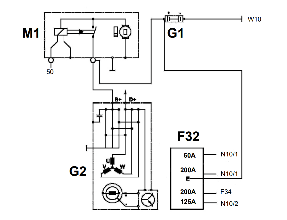
F32 - Pre-fuse block - Pre-fuse block.
F34 - Fuse block - Fuse block.
G1 - Battery - Battery.
G2 - Generator - Generator.
M1 - Starter - Starter.
N10/1 - Front SAM.
N10/2 - Rear air defense system.
W10 - Battery ground - Battery ground.
50 - Starter signal.
Battery
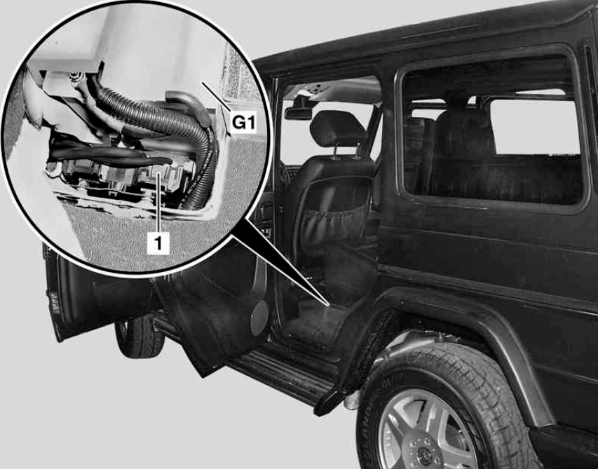
Battery (G1):
• AGM (absorbing glass mat) AGM (absorbing glass mat) - 12 V 90 Ah.
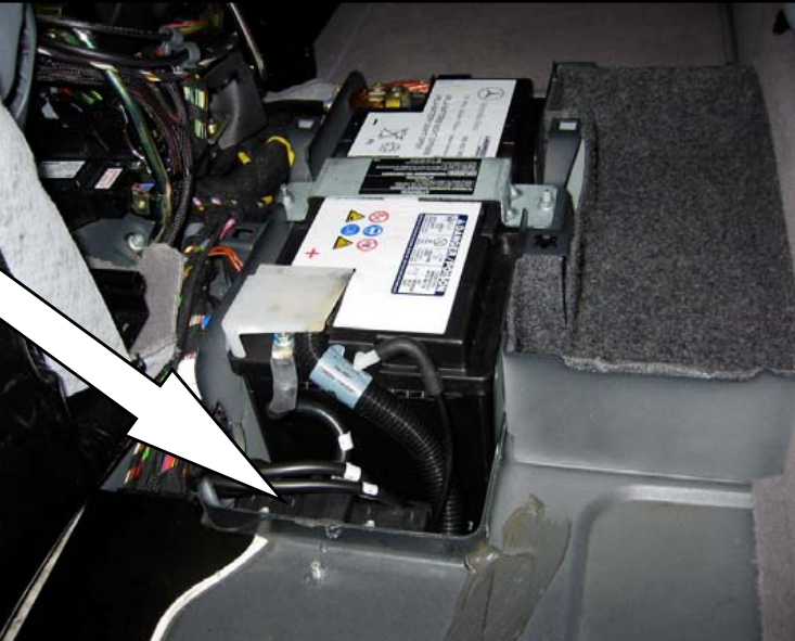
Pre-fuse block (F32):
• Electricity distribution point Electricity distribution point
• Reducing the risk of fire Reducing the risk of fire in an accident in an accident
• Fuses are not replaceable Fuses are not replaceable.
GM / VRLA battery design
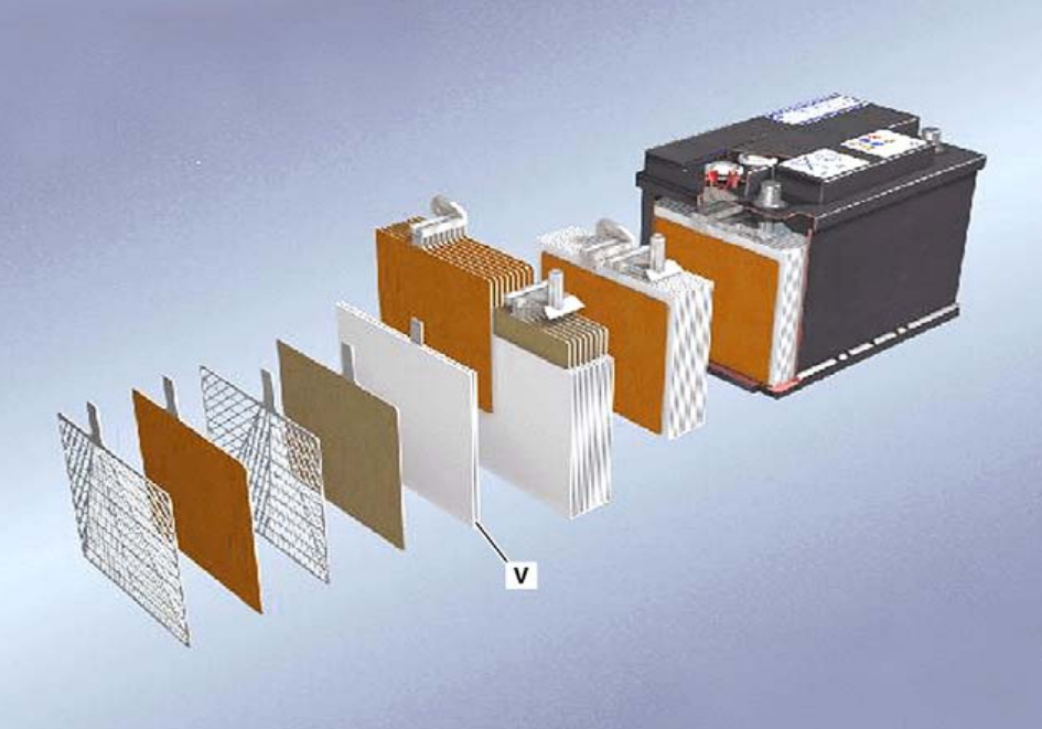
The main design differences between an AGM battery and a regular standard lead-acid battery are:
• Fully hermetic body construction.
• No liquid electrolyte.
• The absorbent glass mat (V) keeps the electrolyte in theAbsorbing glass mat (V) keeps the electrolyte in contact with the positive and negative plates in contact with the positive and negative plates.
• The vent valve is usually sealed, there is no gas.
• The vent valve opens only if the internal pressure exceeds the set level.
AGM / VRLA battery properties
• Longer service life.
• Improved cold start.
• Improved deep cycle.
• No liquid acid spills or leaks.
• Fast recharge time.
• Completely maintenance free.
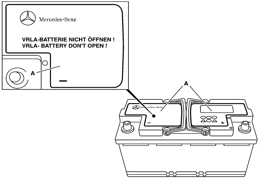
How to identify an AGM battery: How to identify an AGM battery:
• Battery label (VRLA);
• Without filling caps;
• No trace of filling.
AGM / VRLA battery testing
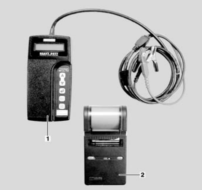
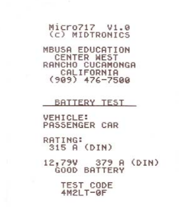
• AGM batteries cannot be tested using the previous methods (load and use methods (load and acid density test).
• New Midtronics MC717 R tester and printer required.
• Discard the acid density sheet and enter the test code (write down and enter the test code) on the warranty claim forms.
• A battery replaced under warranty must have a test printout attached to the RO
• Detailed information on testing, testing and usage of the MCR717 can be found in WIS SI54.10-P-0003-01 WIS SI54.
Location of fuses and relays

Fuse block F2 and F34
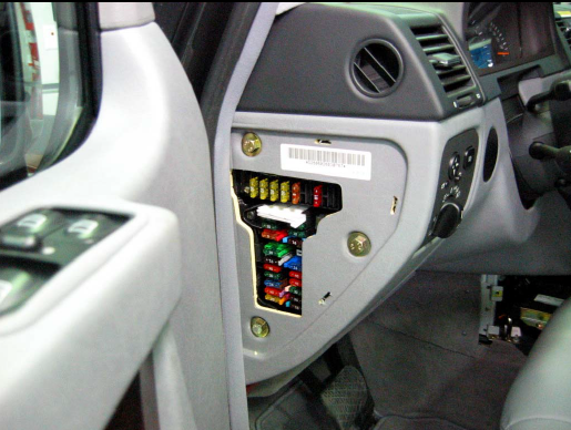
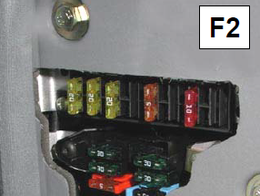
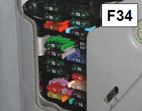
Location: left instrument panel (cover removed).
Note: Fuse diagram can be found in F34.
Front SAM (N10/1)
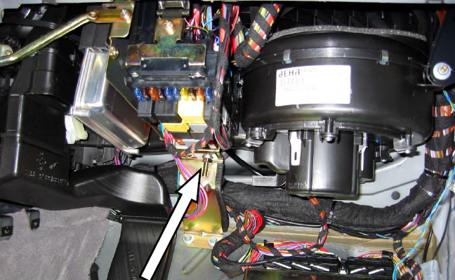
Location: under the dashboard on the passenger side.
Rear SAM (N10/2)
• Rear SAM fuses are accessible on the right side.
• The right front seat fuse is located in F34 (to the left of the instrument panel).
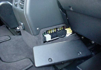
• The rear SAM is located under the center console.
• Additional relays (i - v) above the rear SAM are not accessible through the cover.
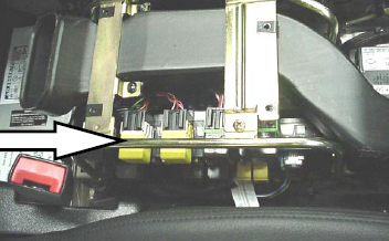
Additional relays
T - ballast of the transmission output speed sensor (N36)
U - central trunk door lock (K44)
V - Rear window wiper (K68).
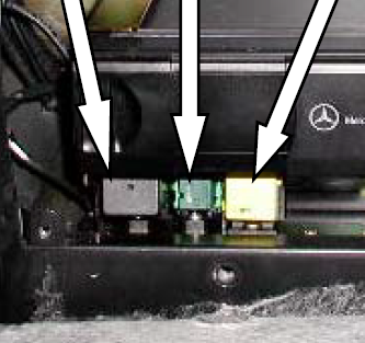
Location: left rear trunk.
Chain
Network based on W203.
Note: Configuration of D2B components - see TI-82.70/185A.
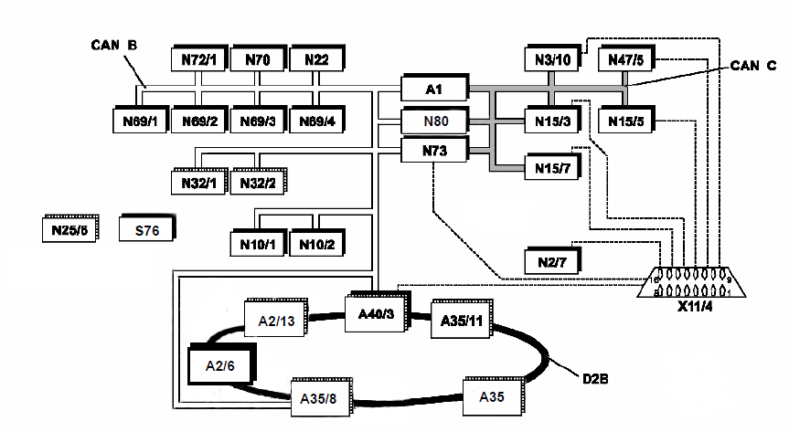
CAN B scheme
CAN voltage H = ~ 0 volts (sleep mode) ~ 0.65 volts (active).
CAN voltage L = ~11 volts (sleep mode) ~4.65 volts (active).
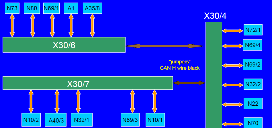
Connector CAN B X30/6
Most CAN wires are marked with German abbreviations near the plug connector. Location: Under the driver's dash (shown with dash removed).
EZS - Electronic ignition switch (N73) Combi - Instrument cluster (A1).
E-Call - TELE AID - Switch on X30/4.
TSG - LF Door control module (N69/1) - Steering column module (N80).
Location: Under the driver's dash (shown with trim removed) EZS.
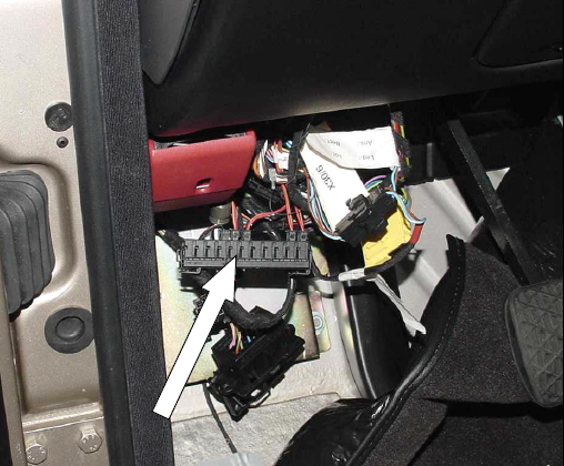
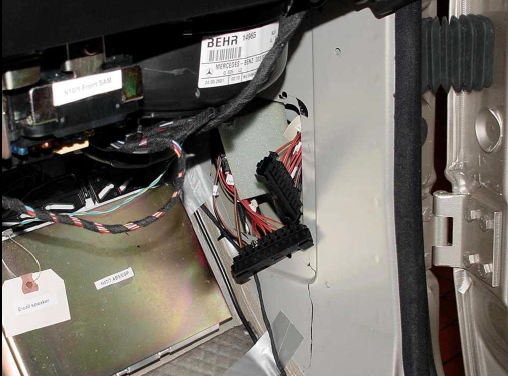
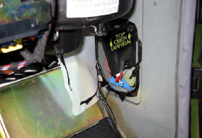
CAN B connector X30/4 and X30/7
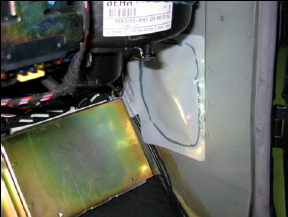
Location: on the front panel of the passenger behind the waterproof sheet.
CAN C connector (X63/4)
EZS - Electronic ignition switch (N73).
Kombi - Combination of devices (A1).
ME - control module ME-SFI (N3/10).
VGS - Distribution control module (N15/7).
EWM - Electronic Gear Shift Module (N15/5) - ESP Control Module (N47/5).
NAG - ETC module (N15/3) - steering column module (N80).
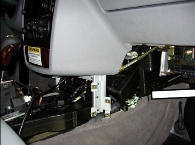
Location: to the right of the center console.
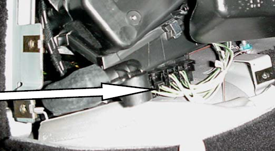
Phone and GPS antenna
A2/22 Front edge of the roof:
• Portable phone.
• Backup TELE AID.
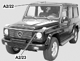
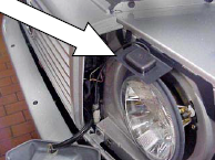
A2/23 On the frame of the left headlight:
• GPS antenna for NAV & TELE AID.
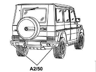
A2/50 Rear bumper end caps:
• TELE AID primary.
AM/FM antenna
A2/18 Rear left window:
• Antenna in the window.
• Amplifier.
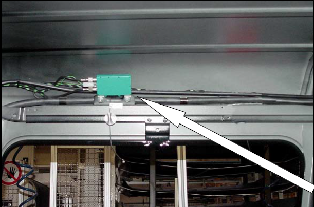
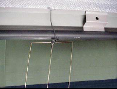
Antenna and amplifier of the central lock
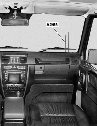
Antenna in the windshield:
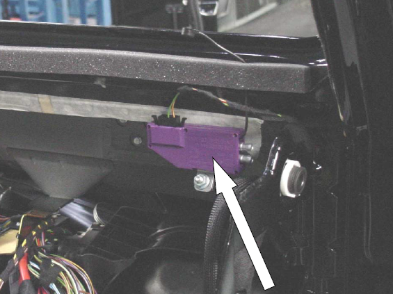
Amplifier near the windshield on the right side:
Electric central locking
• RF antenna on the windshield.
• IR receiver only in LF door.
• Door closing is controlled by micro switches in the door latches.
• The engine of the central door lock is built into the latches.
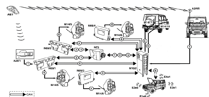
Alarm system against car theft
• The rear SAM is the main ATA module.
• Hood contact switch (not a microswitch).
• Door latch microswitch in the latch.
• The alarm siren is connected to the rear SAM.
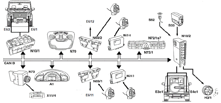
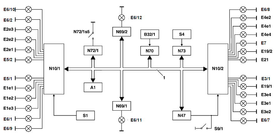
Outdoor lighting
• Circuit protection with electronic fuses in SAM.
• 1 reverse light lens (right side).
• 1 rear fog lamp lens (left).
• Bulb replacement for rear lights only (turn on brake lights using PWM).
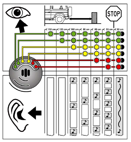
Reversible agent (BA)
Distance warning system when reversing at low speed.
Warns the driver:
- visually;
- by way of sound notification.
Location: Right rear D pillar.
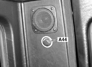
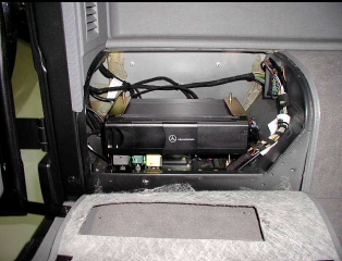
BA control module and sensors
Reverse control module (N62), located in the left rear cargo compartment (near the CD changer):
• Evaluates signals from rear bumper sensors.
• Uses a warning light (A44).
• No self-diagnosis.
• SDS / DAS has controlled tests.
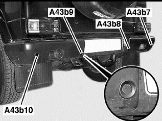
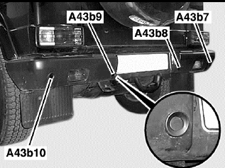
Rear bumper sensors (A43/_):
• 4 ultrasonic bumper sensors.
• Optimum sensor range 11 - 70 inches.
Multi-contour driver's seat (MCS)
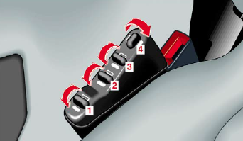
Adjust the volume of air in the various bladders in the driver's seat using the control valve:
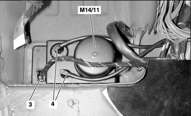
• The MCS pump (M14/11) supplies air volume to the control valve as needed.
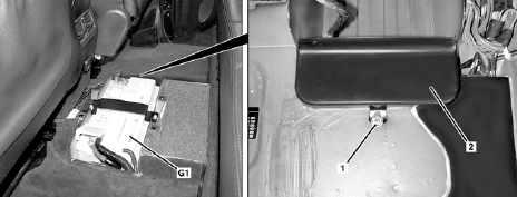
• M14/11 is located under the cover (2), on the right side of the battery (G1).