History of Daewoo Nexia Diagnostics, or why Daewoo Nexia did not work well

AvtoAd
15/10/2023
- Prehistory
- Check for mechanical damage of EBC
- Attempts at computer diagnostics
- Self-diagnosis using flashing codes
- Checking the wires, the sensor, the MAP line
- We started to check the wiring
- Checking the wire under load
- Fault detection
Prehistory
The car arrived with the classic problem of loss of power and irregular engine operation, in most cars the diagnostic process begins with a customer survey and computer diagnostics through the diagnostic connector. Both in the first and in the second case, I did not get the desired result, the client said that it just started working poorly in the morning, and Launch diagnostics did not show anything, as I did not try to go through all possible protocols and reading options.
Check for mechanical damage of EBC
Since the corrosion damage to the thresholds was found, I decided to check the control unit itself for moisture, since it is located on the bottom right and a damaged threshold could have caused a jamming and damage to the unit or connectors.
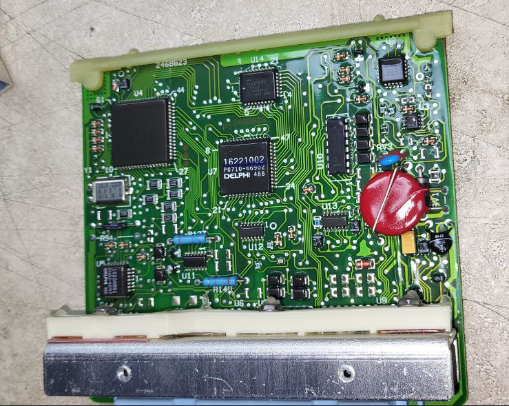
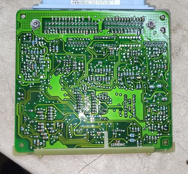
A preliminary and detailed inspection showed that the unit was intact, no burnt or burned elements were found, the chips and wiring in the computer area were also normal. I put everything back together and continued trying to diagnose the unit.
Attempts at computer diagnostics
Brought all the adapters collected during work and continued trying.
Connection diagram

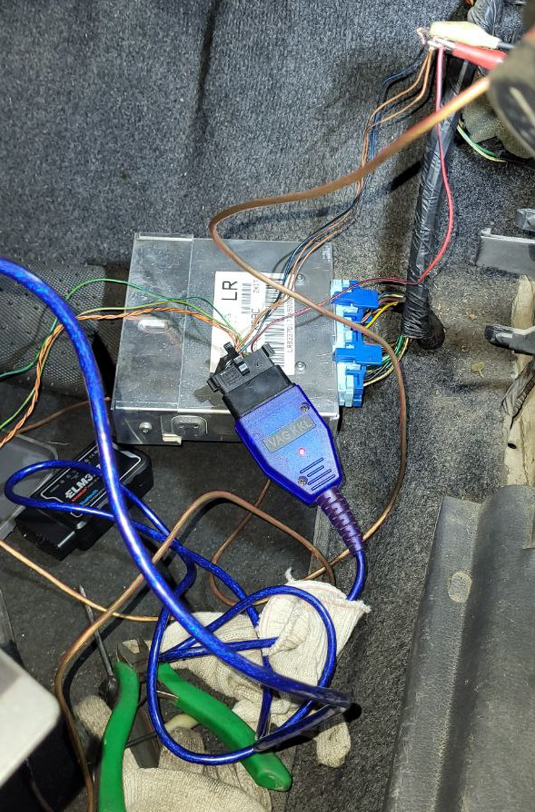
I downloaded all the programs from the excellent site that could diagnose the Nexia, but all the programs and all the adapters or I did not cope with this task.
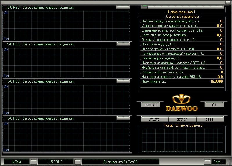
There were still ELM and other adapters, I found many articles on the Internet where they could not diagnose for one reason or another. I used all possible adapters and adapters and realized that I would not be able to diagnose and read errors. Probably not enough competence)) Although in fact Daewoo cars support a low (10400-14400) data transfer rate for communication with EBC and the diagnostic program. Therefore, the adapters must be made on the FT232RL chip in that the FT232BL works with a non-standard speed of 10400. I did not have this. But I realized this later). About such an adapter.
Self-diagnosis using flashing codes
I decided to go the other way and started diagnostics using the so-called blink codes.
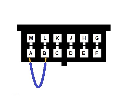
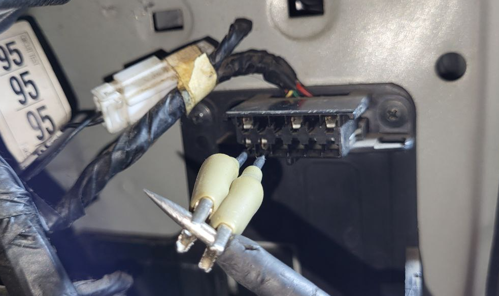
I closed two contacts and turned on the ignition. Everything happened as written in the instructions. The fan turned on, the check engine light began to flash, informing about fault codes, and code 34 was read.
The entire list of codes.
Self-diagnosis code 34 - Absolute pressure sensor in the intake manifold (DAT) - low voltage. Of course, let's go check the sensor.
Checking the wires, the sensor, the MAP line
First, they checked the vacuum tube connecting the sensor and the intake manifold, it turned out to be intact. We continued and started checking the wires, the chip and the sensor.
First, the extreme contacts were checked, there was ground on one, i.e. minus, and + 5 Volts on the other, which corresponded to the norm. The MAP vacuum sensor in this car runs on 5 volts.
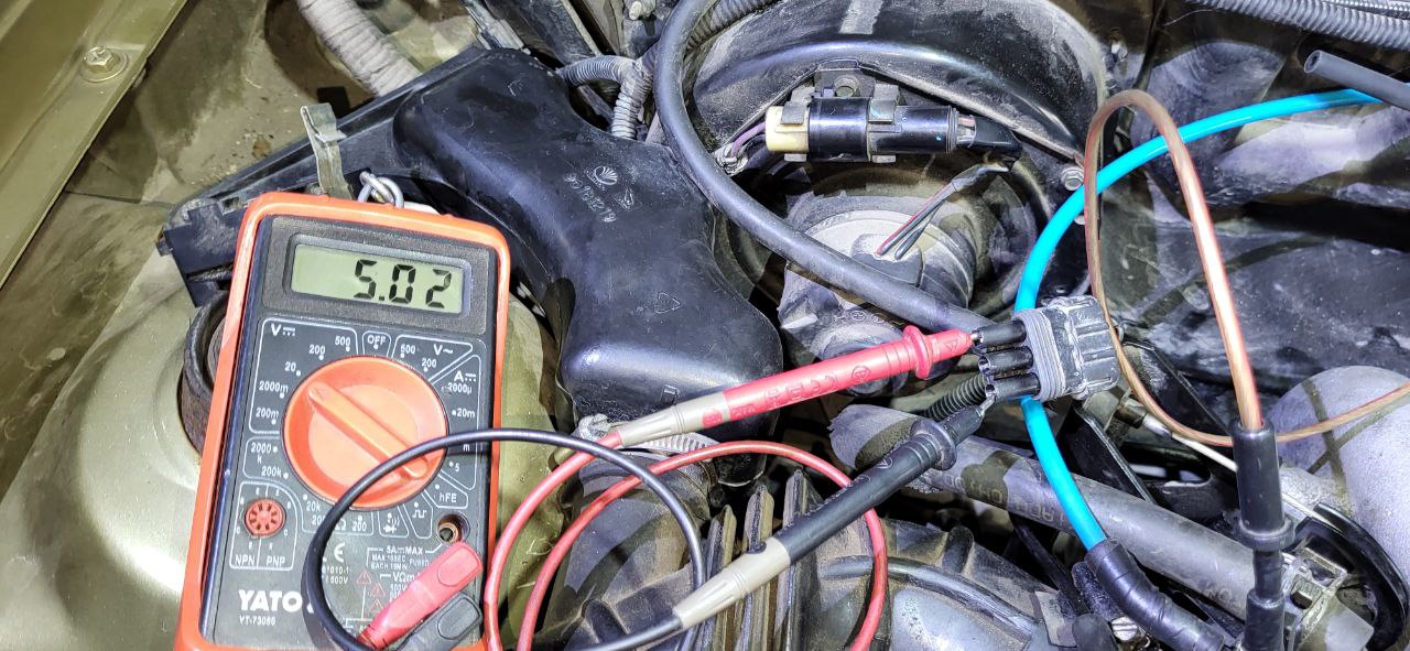
The central one was the output from the sensor and we checked it as well
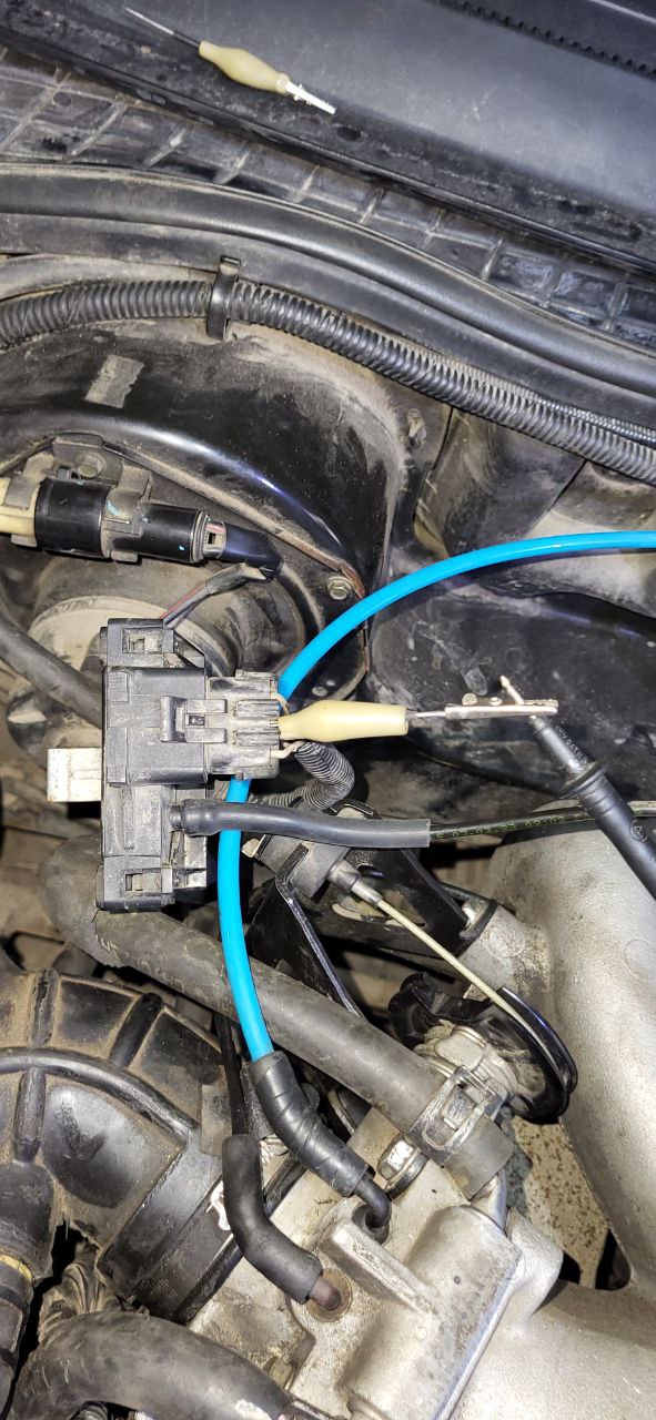
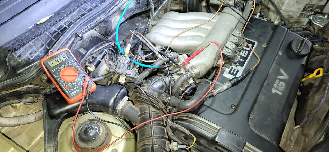
I mixed up the polarity of the probes when checking, but I was not interested in the polarity, I was interested in the behavior of the sensor and the voltage that comes from the sensor when the vacuum in the intake manifold changes. With the engine stopped, the voltage was 4.69 volts.
After starting the engine and manipulating the throttle to create more vacuum, the sensor showed adequate indicators, with a greater vacuum there was a lower voltage and vice versa.
The approximate readings of the MAP sensor were as follows:
- Stopped engine 4.7 Volts
- The engine is running at idle speed of 3.6 Volts
- Sharply open the 4.6 Volt throttle
- Creation of rarefaction (after revving the engine, close the throttle sharply) 1.32 Volts
From what it became clear that the sensor is normal, at least it looks like that)
Started checking wiring :
First, they found and checked with a tester, everything is fine, the resistance of only the wires is 0.2 Ohm.

It happens that a damaged wire can be oxidized and the tester checks well, but when the load is connected, the indicators change dramatically. Although we have a signal wire, we need to check it properly. After all, not only the voltage load changes the data, but also the humidity and temperature of the environment. Therefore, I decided to test under a load of 50 watts.
Checking the wire under load :
Additionally, a 50 W lamp was connected to this wire to verify the integrity of this wire. This work can be divided into stages. But be careful, incorrect actions can lead to damage to car components.
- disconnected the sensor
- disconnected the control unit
- make sure that this wire is not connected to anything else, according to the diagram or tester
- on one side, for example, from the side of the EBK, a mass (-12 Volt) was applied
- on the other side, from the side of the MAP sensor chip, connect one of the contacts of a 50 watt light bulb
- connect the second contact of the light bulb to +12 volts of the battery. The light bulb should glow at full intensity.
- disconnect the lamp contact from the sensor wires and connect to the -12 Volt terminal of the battery. The bulb should glow as brightly as when connected to the sensor wires.
In my case, the wire was intact.
To summarize: The sensor is intact, the tubes are intact, the wiring is intact, the control unit looks functional and does not cause suspicion.
I decided to question the ignition angle and the timing mechanism, if the belt jumped, then the vacuum formation will not form properly. Therefore, I asked the mechanics to check the correctness of the timing belt (gas distribution mechanism) labels. And separately, the tightening force of the crankshaft pulley of the generator belt. This pulley has teeth from which the position and speed of the crankshaft is read. When replacing the timing kit, the appropriate tightening moments may not be observed and the bolt loosens, after which, in the best case, the ignition is displaced and everything can be fixed with new pulleys and a sprocket, or the timing belt turns and a salad of valves, crackers, springs, pistons is formed... valve'.
Malfunction detection :
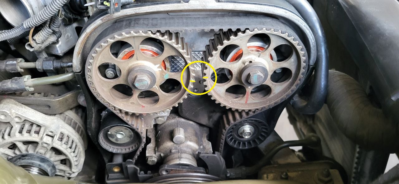
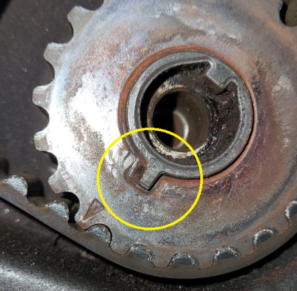
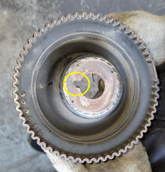
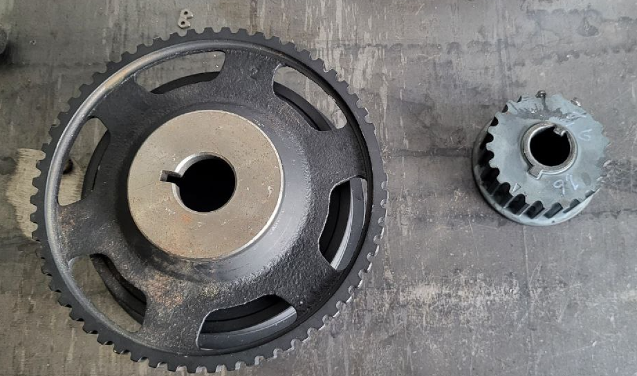
And here we have the result, the pulley was really shifted by 2 teeth, which is a lot. In addition, the crankshaft sprocket seats for the timing belt and the crankshaft pulley seat were broken. Another camshaft was shifted, but only by one tooth.
Camshafts:
Crankshaft timing drive:
Crankshaft pulley:
Of course, everything was replaced and collected according to the tags.
New spare parts:
After the replacement, the car started perfectly and ran without any problems. The client is happy, the craftsmen are satisfied)))
Good mood and successful repairs to everyone!