ESP program for Audi

AvtoAd
28/09/2022
The design and operation of the ESP Audi electronic stabilization program
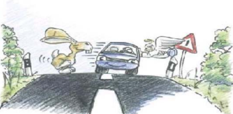
The system is designed to help the driver in difficult road situations - for example, when an animal suddenly appears on the road, when it is necessary to reduce the load and avoid instability in driving the car. At the same time, ESP does not help to outwit the laws of nature, thus opening the way for miscreants. A careful driving style and attention to other road users remain the main tasks of the driver. In this article, we will describe how ESP works together with the already proven anti-lock braking system ABS and its "relatives" ASR , EDS , EBV and MSR and which system options we install on different vehicles.
Content
1. Introduction .
2. What is ESP .
3. Advantages of ESP .
4. About ABS .
5. About ASR .
6. About EBV .
7. About EDS .
8. About ESP .
9. About MSR .
10. About BOSCH and ITT Automotive Systems .
11. Physical foundations : force and moment.
12. Adjusting dynamics .
13. Overview of the BOSCH system .
14. Structure and functions of ESP .
15. Automatic adjustment system .
16. ABS control unit with EDS/ASR/ESP J104 .
17. Sensor of the angle of rotation G85 .
18. Transverse acceleration sensor G200 .
19. Sensor of the angle of rotation G202 .
20. G200 lateral acceleration sensor and G202 rotation angle sensor .
21. Brake pressure sensor G201 .
22. ASR/ESP switch E256 .
23. Hydraulic dynamics adjustment pump V156 .
24. Hydraulic unit .
25. BOSCH functional diagram .
26. Diagnostics .
27. Control lamps and diagnostic buttons .
28. Overview of the ITT-Automotive system .
29. ESP device and functions .
30. ABS control unit with EDS/ASR/ESP J104 .
31. Sensor of the angle of rotation G85 .
32. Transverse acceleration sensor G202 .
33. Sensor of the angle of rotation G202.
34. Longitudinal acceleration sensor G249 .
35. ASR/ESP switch E256 .
36. Active amplifier of braking force with the master cylinder .
37. Block of piston valves .
38. Functioning of the ESP braking detection switch .
39. Hydraulic unit .
40. Functional diagram of ITT-Automotive .
41. Diagnostics .
42. Warning signals and diagnostic sensors .
43. Maintenance .
Introduction
With the development of the automobile industry, more and more powerful cars appear on the market. As a result, designers face the question of how to make this technique controllable for a "normal", average driver. In other words, what systems need to be developed to provide optimal braking and relieve the driver of overload? Already in the twenties and forties, the first mechanical predecessors of the ABS system appeared, which, due to their increased inertia, could not fully fulfill the task. After the revolution in the field of electrical engineering in the 60s, ABS systems became more accessible and continued their development already based on digital technology, so nowadays not only ABS, but also systems such as EDS, EBV, ASR and MSR are common car equipment . The pinnacle of development of these systems is ESP, where engineers have gone even further.
What is ESP?
The electronic stabilization program is an active means of car safety. In this we can talk about the system of dynamics. Simply put, this is an anti-skid system. It recognizes the danger of skidding and deliberately compensates for the car's turn.
Advantages of ESP :
- It is not a separate system, it is installed on other traction systems, thus absorbing their best qualities.
- The load is removed from the driver.
- The car remains under control.
- The risk of an accident due to the driver's inappropriate reaction to what is happening is reduced.
About ABS
The anti-lock system prevents the wheels from locking when braking. Despite the high braking efficiency, the car remains stable and manageable.
About ASR
The traction control system prevents the traction wheels from slipping, for example on ice or gravel, by applying the brakes or engine control.
About EBV
Electronic brake force redistribution prevents the rear wheels from braking before the ABS kicks in, or if the ABS fails.
About EDS
The electronic differential lock allows you to start moving on different sections of the road by braking the slipping wheels.
About ESP
The electronic stabilization program prevents possible shaking of the car by influencing the brakes and engine control. The following abbreviations are also used:
ASMS - automatic stabilization control system;
DSC - dynamic stabilization control;
FDR - dynamic adjustment;
VSA - automobile stabilization device;
VSC - vehicle stability control.
About MSR
Towing torque control prevents the drive wheels from locking in the event of engine braking, when the accelerator pedal is suddenly released, or braking occurs with the gear engaged.
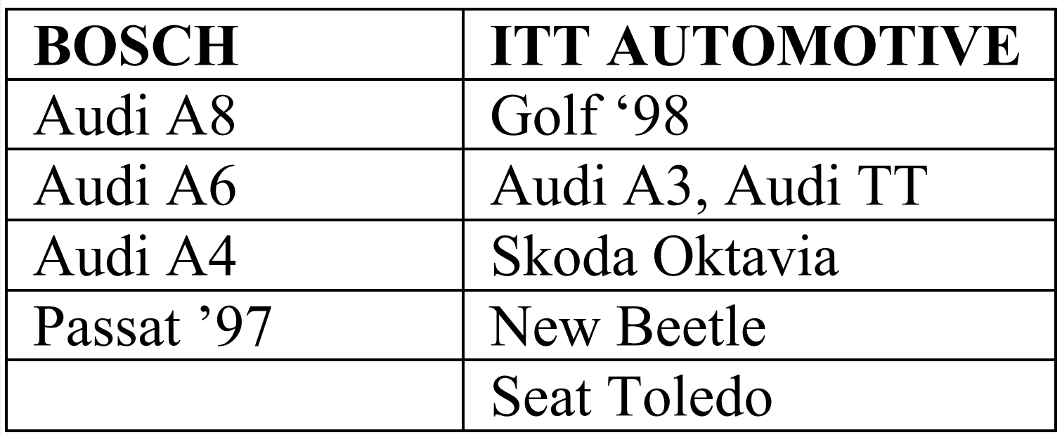
BOSCH and ITT Automotive systems are used by the concern, installed on various car models:
To prevent skidding, a dynamics system such as ESP must instantly affect the brakes. The increase in pressure occurs with the help of the ABS return pump. To improve pump performance, sufficient pressure must be created on the suction side of the pump. The main difference between the BOSCH and ITT Automotive systems lies in the method of creating initial pressure.
BOSCH
In the BOSCH system, the initial pressure is created with the help of a hydraulic dynamics adjustment pump, which is located under the hydraulic unit in the common holder. The ESP control unit is separate from the hydraulic unit.
ITT Automotive
In the ITT AUTOMOTIVE system, the initial pressure is increased by an active brake booster. The hydraulic unit and the control device are parts of the same unit.
Physical foundations: forces and moments
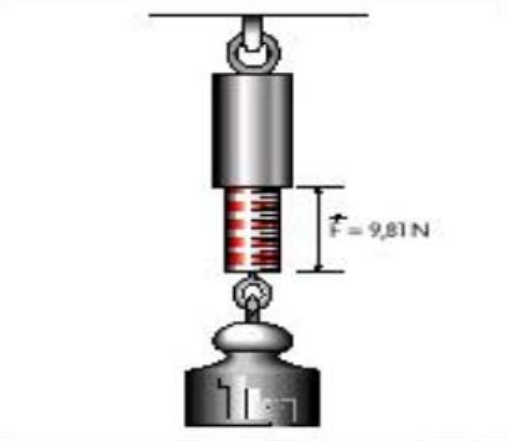
Any body is exposed to various forces and moments. If the sum of the forces and moments acting on the body is zero, the body is at rest, if it is not zero, the body moves in the direction of the force, which is the result of the addition of forces. The most famous force is gravity. It acts in the direction of the center of the Earth. If a body with a mass of one kilogram is placed on a spring scale to measure the forces acting on it, it will show a value of gravity of 9.81 newtons.
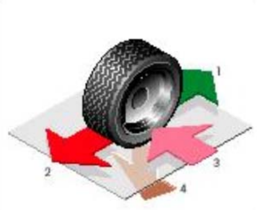
Other forces acting on the car are:
- traction force (1),
- braking force (2) acting in the direction opposite to the direction of the traction force,
- lateral forces (3) that support vehicle controllability,
- the force of adhesion (4), which, among other things, is a consequence of friction and the Earth's gravity.
In addition, the car is subject to:
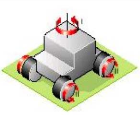
- the yawing moment (I), which tends to turn the car around the vertical axis,
- the moment of inertia (II), which tends to maintain the chosen direction of movement,
- and other forces, such as air resistance.
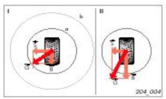
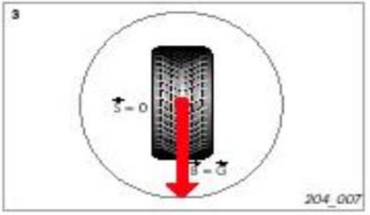
The joint action of several of these forces is easy to describe with the help of a friction circle. The radius of the circle is determined by the force of adhesion of the tires to the road surface. The smaller the grip, the smaller the radius (a), with good grip the radius is larger (b). The basis of the friction circle is the parallelogram of forces (lateral force (S), braking force or traction gain (B) and total resultant force (G)). As long as the total force remains inside the circle, the car is in a state of stability (I). As soon as the total force goes beyond the boundary of the circle, the car loses controllability (II).
Let's turn to the diagram of the interaction of forces:
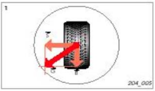
1. Braking force and lateral force are calculated so that the resultant force remains within the circle. The car is easy to drive.
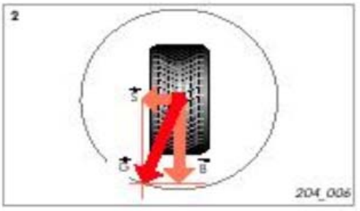
2. Let's increase the braking force. Lateral force is reduced.
3. The resulting force is equal to the braking force. The wheel is locked. Due to the lack of lateral force, the car becomes uncontrollable. A similar situation arises with regard to traction force and lateral force. If the value of the lateral force approaches zero due to the maximum increase in the traction gain, the driving wheels slip.
Dynamics adjustment
Adjustment mode
In order for the ESP system to be able to influence critical situations, it must recognize two points:
- where and at what speed is the driver directing the car?
- Where is the car going?
The system receives the answer to the first question from the steering angle sensor (1) and wheel speed sensors (2). The system receives the answer to the second question from the yaw rate (3) and lateral acceleration (4) meter.
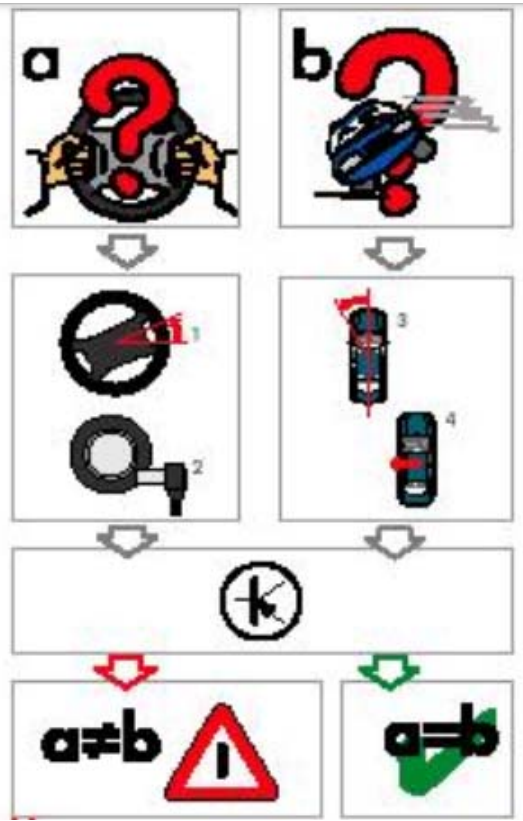
If the information received on two points does not match, the ESP system recognizes the situation as critical and takes action.
A critical situation can be expressed in two possible ways of driving:
1. Lack of attention to driving. By means of a directed action on the rear brake on the inside of the turn and influencing the control of the engine and gearbox, the ESP system prevents the car from drifting out of the corner.
2. Excessive attention to driving. By means of a directed action on the front brake on the outside of the turning trajectory and an influence on the control of the engine and gearbox, the ESP system prevents the side of the vehicle from skidding.
As you have already seen, ESP can counter insufficient or excessive attention to driving. For this, it is necessary to change the direction of movement without directly influencing the control. The basic principle is familiar to you from tracked machines. If the car has to turn left, the circuit inside the turn decelerates, and the outer one reports acceleration.
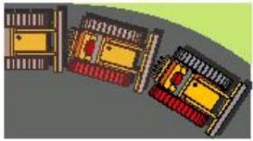
When returning to the initial trajectory, the former "inner" track accelerates, and the "outer" one slows down.
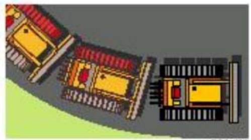
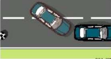
ESP also works according to the corresponding principle. First, consider an example of a car not equipped with an ESP system. The car must dodge an obstacle that suddenly appeared. The driver first turns sharply to the left, and then to the right again.
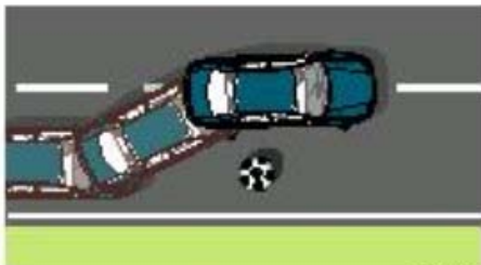
A vibration is created and the rear part breaks off from the trajectory. Turning around the vertical axis can no longer prevent the driver.
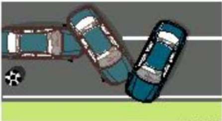
Now consider an example of a car equipped with an ESP system
The driver tries to avoid obstacles. According to the sensors, the ESP system recognizes the unstable condition of the car. The system calculates the necessary measures: the left rear wheel brakes. In this way, the vehicle is prevented from skidding. The lateral force acting on the front wheels is preserved.
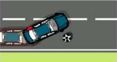
While the car makes a left turn, the driver turns right. ESP brakes the front right wheel. The rear wheels rotate freely to ensure optimal lateral force action on the rear axle.
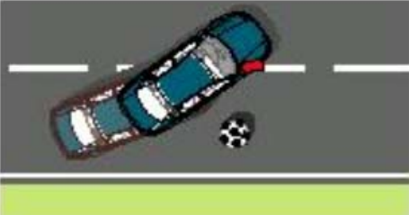
A lane change that has taken place may cause vibration. To prevent the rear of the vehicle from skidding, the left front wheel is braked. In particularly critical situations, the wheel can practically lock to limit the impact of lateral force on the front axle.
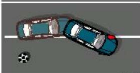
Once the car has overcome the instability, ESP stops influencing the steering.
Overview of the BOSCH system
As already mentioned, the electronic stabilization system is installed on common and used anti-lock braking systems. In addition, it significantly expands their effect: the system can recognize and neutralize unstable conditions of the car , such as skidding. Some additional details are required to ensure this procedure:
1. Control device.
2. Brake booster.
3. Brake pressure sensor.
Important : Volkswagen cars use ESP systems from two manufacturers. These are BOSCH and ITT-AUTOMOTIVE. The systems are identical in function and structure, but have slightly different components. When replacing parts, pay attention to which system you are dealing with.
BOSCH
The ABS control unit with EDS/ASR/ESP J104 is located in the right front passenger footwell on the front body wall.
Sensors:
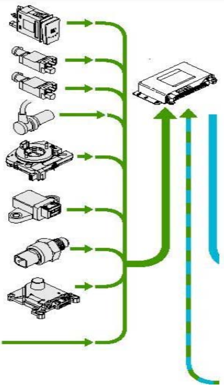
- ASR/ESP probe E256 .
- Brake light switch F .
- Brake pedal switch 47 .
- Wheel speed sensor:
rear right G44 ;
front right G45 ;
rear left G46 ;
front left G47 .
- Sensor of the angle of rotation G85 .
- Transverse acceleration sensor G200 .
- Brake pressure sensor G201 .
- Speed sensor G202 , located in the footwell of the front passenger on the left, in front of the central comfort system.
- Additional signals:
- Engine management;
- Control of the gearbox.
Components:
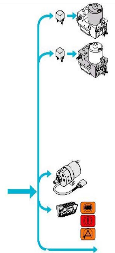
- Rotary pump relay - ABS J105, in the protective casing of the control devices, in the engine compartment, front right.
- ABS V39 rotary pump.
- Solenoid valve relay - ABS J106, in the protective casing of the control devices, in the engine compartment, front right.
- ABS intake valves N99, N101, N133, N134.
- Exhaust valves ABS N100, N102, N135, N136.
- Switching valve -1- adjustment of dynamics N225.
- Switching valve -2- adjustment of dynamics N226.
- High-pressure switching valve – 1- adjustment of dynamics N227.
- High-pressure switching valve - 2- adjustment of dynamics N228.
- Hydraulic pump for adjusting dynamics V156.
- The display unit control device in the control panel unit J285.
- Control lamp ABS K47
- Brake system control lamp K118
- Control lamp ASR/ESP K155.
- Additional signals.
- Engine management.
- Control of the gearbox.
- Management of the navigation system.
Structure and functions of ESP
Automatic adjustment system
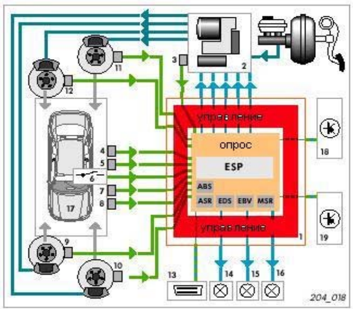
1. ABS control device with EDS/ASR/ESP.
2. Hydraulic unit with pre-charge pump.
3. Brake pressure sensor.
4. Transverse acceleration sensor.
5. Sensor of the angle of rotation.
6. ASR/ESP button.
7. Angle of rotation sensor.
8. Brake light switch.
9-12. Speed sensors.
13. Diagnostic block.
14. Brake system malfunction control lamp.
15. ABS control lamp.
16. Control lamp ASR/ESP.
17. Driver-car mode of operation.
18. Effect on engine control.
19. Effect on transmission control (automatic transmission only).
Speed sensors constantly transmit signals with information about the speed of rotation of each wheel. The steering wheel rotation sensor is the only sensor that transmits data directly via CAN-Bus to the control unit. The totality of the mentioned data allows to calculate the given direction of movement and optimal driving characteristics of the car. The lateral acceleration sensor "warns" the control device about a lateral turn, the rotation frequency sensor - about possible skidding. Based on this data, the current condition of the car is determined. If these characteristics do not match, the degree of intervention required is calculated.
ESP "decides":
- which wheel should be notified of deceleration or acceleration and to what extent,
- should the engine torque be reduced,
- in the case of an automatic gearbox, should there be an influence on the gearbox control.
Then the system checks according to the readings of the sensors whether the impact was successfully carried out:
With a positive result, the influence is stopped, and monitoring of the car's progress continues. If it is negative, automatic regulation continues. In the case of influencing the control of the car's systems, the driver will know about this flashing of the ESP signal.
ABS control unit with EDS/ASR/ESP J104
In the BOSCH system, the control device is separated from the hydraulic unit. It is located in the footwell of the front passenger on the right.
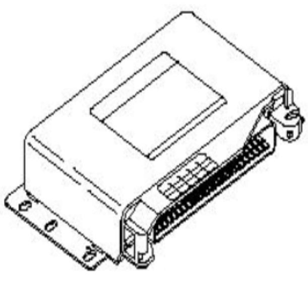
Structure and functions
The system contains a powerful microcomputer. To ensure a high and necessary degree of adjustment accuracy, the system consists of two computing units, its own voltage monitoring device and a diagnostic device. Both computing units use the same software to process information and perform mutual monitoring. Cases of equipment of such a dual system are called active reserve.
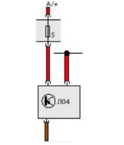
Automatic connection
Control device J104 is supplied by the voltage of the positive connection in the control panel line circuit.
Consequences of breakdowns
In the unlikely event of failure of all components of the control device, the standard braking system without ABS, EBS, ASR and ESP remains at the disposal of the driver.
Diagnostics
The following types of damage are recognized:
- Damage to the control device;
- Errors in the supply voltage.
Sensor of the angle of rotation G85
It is located in the steering column between the gear shifter and the steering wheel. The turning ring with the contact ring for the driver's airbag is built into the steering angle sensor and is located on the underside.
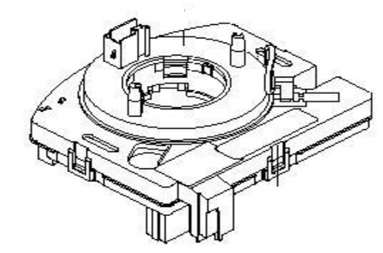
Appointment
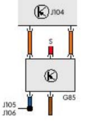
The sensor transmits the steering wheel angle data to the ABS control unit with EDS/ASR/ESP. The perception range is ±720º, which is four full turns of the steering wheel.
Electronic activation
The G85 is the only sensor in the ESP system that transmits data directly via the CAN bus to the control unit. After turning on the ignition, the sensor is initiated as soon as the steering wheel turns 4.5º, which corresponds to a turn of about 1.5 cm.
Consequences of failure
Without information from this sensor, the desired direction of movement cannot be calculated. The ESP function turns off.
Diagnostics
After replacing the control device or the sensor, the zero position of the sensors must be calibrated.
- information is not received from the angle of rotation sensor,
- wrong setting,
- mechanical error,
- damage,
- Implausible signal data.
Important : errors may occur when the track is changed. Observe the necessary connection between the sensor and the steering wheel.
Building
The angle is measured according to the photo cell principle (overlapping of the light flux).
The main components are:
- light source (a),
- coding washer (b),
- optical sensors (c+d) and
- Counter (e) of complete revolutions.
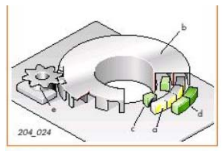
The encoder washer consists of two rings, absolute and rotating (incremental). Both rings are scanned by two sensors.
Functions
Let's simplify the device device by placing absolute (2) and moving (incremental) (1) masks next to each other. There is a light source between the masks (3). Optical receptors (4+5) are located outside.
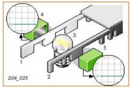
If light falls on the sensor through the gap, a signal voltage is created, the light source is hidden, and the voltage disappears. When the masks are shifted, two consequences are possible. The incremental sensor transmits a constant signal, because the gaps follow each other evenly. Absolute sensor - non-constant signal, because the mask is interrupted unevenly. From the comparison of the two signals, the system calculates how much the masks are shifted. In this, the initial position is calculated from the position of the absolute component.
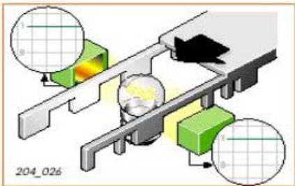
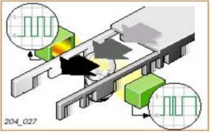
According to a similar principle, but designed for rotational movement, the sensor of the angle of rotation functions.
Transverse acceleration sensor G200
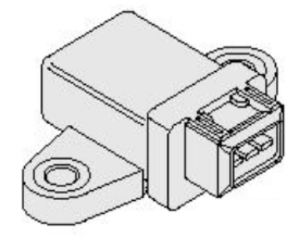
According to the laws of physics, this sensor should be as close as possible to the center of gravity of the car. Therefore, it is built into the footwell under the driver's seat.
Appointment
The G200 transmits data on the distribution of lateral forces acting on the vehicle and tending to change the desired trajectory.
Electronic connection
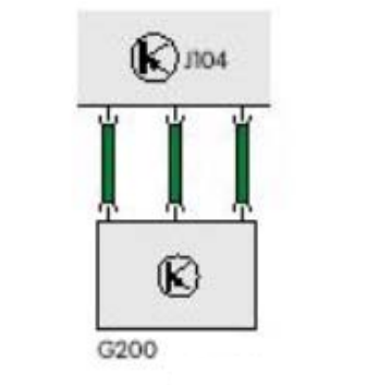
G200 is connected to control device J104 by three electrical cables.
Consequences of failure
Without information from this sensor, the real state of the car cannot be calculated. The ESP function turns off.
Diagnostics
Diagnostics determines gaps in the connection and the presence of a short circuit. The system also monitors damage to the detector.
Device
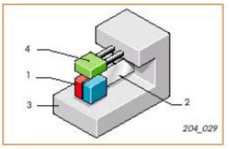
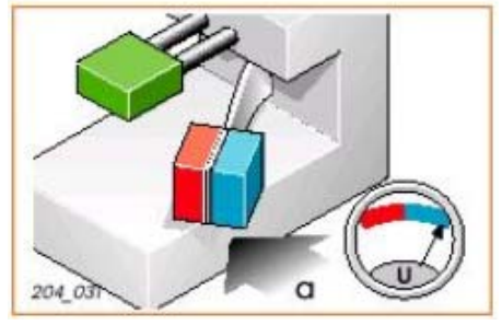
In a simplified form, the transverse acceleration sensor consists of a permanent magnet (1), a spring (2), a damper plate (3) and a Hall sensor (4). A permanent magnet, a spring and a damper make up the magnetic system. The magnet is firmly connected to the spring and can swing over the damper plate.
Functions
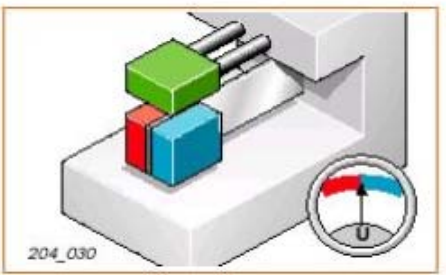
When the car is subjected to a lateral acceleration (a), the permanent magnet, due to its inertia, repeats the motion with a delay. That is, the damper plate and the sensor move together with the car body, while the magnet remains stationary for a moment.
As a result of this movement, electric eddy currents arise in the damper plate, forming a flow counter-rotating in relation to the field magnet. Therefore, the strength of the general magnetic field decreases. This causes the voltage of the Hall sensor (U) to change. The voltage change is proportional to the force of the lumbar acceleration.
This means that the stronger the movements of the magnet and the plate differ, the more the magnetic field weakens and the Hall voltage changes more noticeably. In the absence of transverse acceleration, the Hall voltage remains constant.
Sensor of the angle of rotation G202
This sensor should also be located as close as possible to the vehicle's center of gravity. In Passat '98, it is located in the front left footwell, in front of the central comfort control.
Device
The yaw angle sensor is an invention originally used in space technology. It determines whether the body exerts a torque. Depending on the location, rotation around one of the spatial axes can be defined. In the ESP system, the sensor must determine whether the car is rotating around a vertical axis. This is called turning angle measurement. Until now, BOSCH technologies incorporated a sensor that functioned according to the principle of a gyroscope. However, in the near future it will be replaced by a combined sensor of the angle of rotation, which functions according to a different principle.
Purpose and functions
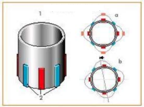
The main component is a small metal hollow cylinder (1). It has eight piezoelectric elements (2). Four create resonant oscillations of the cylinder (a). Four "observe" whether the oscillation nodes of the cylinder, on which they are located, change. This is exactly what happens when a torque acts on the cylinder. Oscillation nodes shift (b). This process is measured by piezo elements, and the data is transmitted to the control device, which calculates the angle of rotation from them.
Transverse acceleration sensor G200 and rotation angle sensor G202
In the future, these two sensors will be combined into one. Such a solution has the following advantages:
- compactness,
- exact correspondence of the operation of two sensors in relation to each other, without the possibility of changing it,
- structural strength.
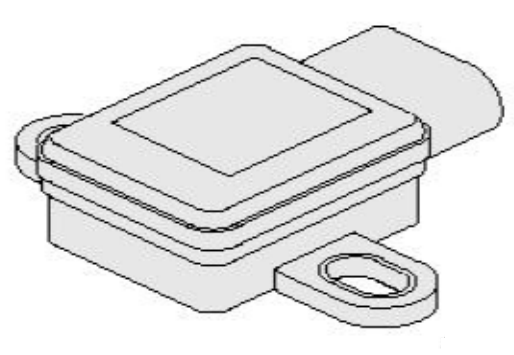
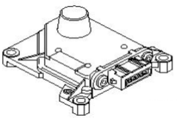
The components are mounted on the main board and function according to the principles of micromechanics. The connection is made using a six-pole plug. The measurement of transverse acceleration is carried out according to the capacitive principle. The turning angle is calculated based on the Coriolis acceleration measurement data. Let's take an example: If, for example, in the northern hemisphere of the Earth, a gun fires, telling the core a horizontal trajectory, it will deviate from it quite noticeably for an observer rotating with the earth. The cause is considered by the observer to be the force that accelerates the core against the direction of the Earth's rotation and displaces it in relation to the straight path - the Coriolis force.
Transverse acceleration sensor device
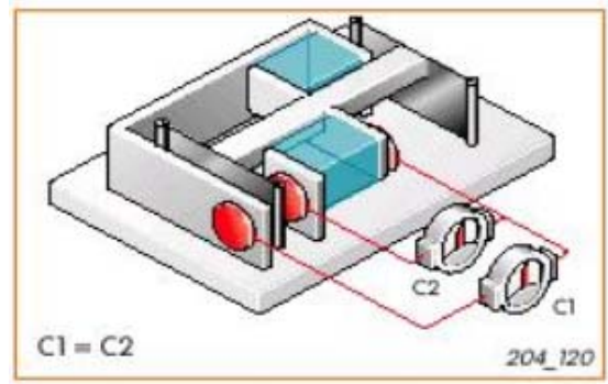
The sensor is a small part on the combined sensor board. In a simplified form, its structure can be imagined as follows: a moving capacitor board with a load is suspended in such a way that
has the ability to fluctuate. Two more capacitor boards are fixed and thus located in relation to the first board, forming two series capacitors K1 and K2. The electrodes can be used to measure the amount of charge that both capacitors can store. This amount of charge is referred to as capacity.
Functions
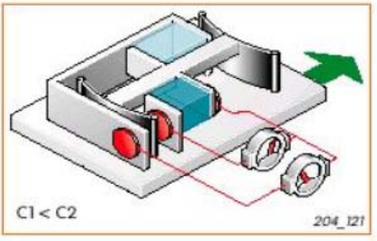
By the time acceleration begins to act on this system, the number of measured charges C1 and C2 in both capacitors is equal. As soon as the lateral acceleration begins to act, the inertia of the load on the middle moving plate causes this part to move relative to the fixed plates in the direction of the vehicle. Thus, the distance between the boards and the amount of charge in the capacitors changes. The distance between the plates of the capacitor K1 increases, the corresponding capacity C1 decreases. The distance between the capacitor plates K2 decreases, the corresponding capacity Z2 increases.
The device of the sensor of the angle of rotation
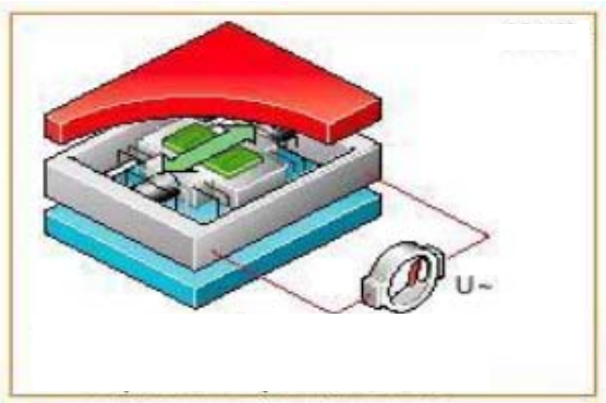
On the same board, remote from the lateral acceleration sensor, there is a rotation angle sensor. The principle of its action is more convenient to consider on a simplified diagram. Suppose that there is a load capable of oscillating in the Earth's permanent magnetic field between the North and South Poles. Notches representing the sensor are applied to it. In this sensor, this structure is duplicated twice for safety purposes.
Functions
At the moment of applying the alternating voltage U, the moving load with applied notches begins to oscillate in the magnetic field.
If rotational acceleration begins to act on this structure, the load, which oscillates due to its inertia, "behaves" in the same way as the core described above. It deviates from the straight path of oscillation due to the effect of Coriolis acceleration. Since this happens in a magnetic field, the electrical parameters of the notches change. Measuring this change determines the strength and direction of the Coriolis acceleration. Computer electronics calculates the angle of rotation based on this value.
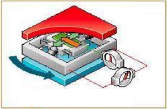
Brake pressure sensor G201
It is included in the hydraulic pump of the dynamic adjustment.
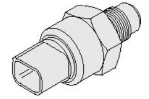
Appointment
The brake pressure sensor informs the control device of the pressure data in the brake system. Based on these data, the control device calculates the forces of the wheel brakes and the longitudinal reinforcement acting on the car. If it is necessary to activate the ESP, the control unit calculates the lateral forces behind them.
Electronic activation
The brake pressure sensor is connected to the control unit J104 by three connections.
Consequences of failure
Without information about the actual pressure, lateral forces cannot be determined. The ESP function turns off.
Diagnostics
Diagnostics determines gaps in the connection and the presence of a short circuit. The system also detects damage to the sensor.
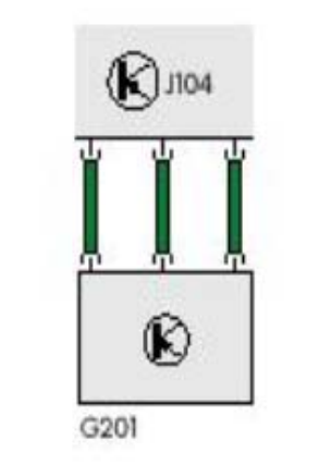
Device
The center of the device contains a piezoelectric element (a), which can be pressurized by brake fluid and an electronic sensor (b).
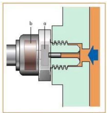
Functions
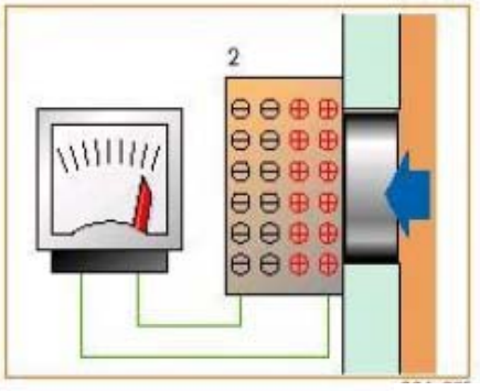
If the brake fluid pressure on the piezoelectric element, the distribution of charges in the element changes. Without pressure, the charges are evenly distributed (1). When a pressure force appears, the charges are spatially distributed (2) and an electric voltage arises.
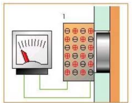
The higher the pressure, the stronger the separation of charges. The pressure is on. The voltage is amplified by the built-in electronics and sent to the device as a signal. The magnitude of the voltage, thus, is a direct measure of the braking pressure.
ASR/ESP switch E256
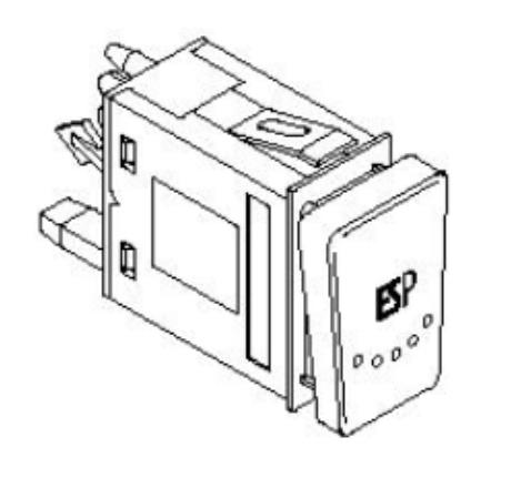
The switch depends on the car model in the area of the control panel. It provides the ability to disable ESP. When you press the brake pedal again or press the corresponding button, it turns on again. If the driver forgets to reactivate ESP, the system restarts itself after starting the engine.
It is advisable to turn off ESP:
- when shaking on deep snow or loose soil,
- when driving with anti-skid chains,
- during the operation of the car on the test bench.
When ESP is active or when the transmission is engaged, this function cannot be disabled.
Consequences of failure
ESP cannot be turned off if the switch is damaged. The signal about malfunctions is located on the control panel.
Diagnostics
Diagnostics does not recognize errors in the operation of the switch.
Electrical inclusion
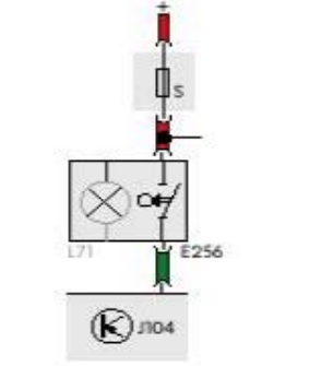
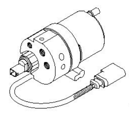
Hydraulic pump for adjusting dynamics V156
It is located under the hydraulic unit in the engine compartment on the general carrier.
Appointment
In the presence of the ABS system, when the brake pedal is pressed, a small amount of brake fluid is released as opposed to high pressure. This function is performed by the return pump. It is also able to provide a large amount of brake fluid, even with little (or no) pressure on the pedal, since brake fluid has a high viscosity at low temperatures. Therefore, the ESP system provides for the presence of an additional hydraulic pump, which creates the necessary initial pressure in the return pump. The precharge pressure is limited by the throttle on the master cylinder. The control dynamics of the hydraulic pump is not adjusted.
Electronic activation
Both hydraulic pump wires are connected to control unit J104.
Consequences of failure
In this case, ESP stops working. ABS, EDS and ASR systems are not affected by this failure.
Diagnostics
Diagnostics recognizes errors only in wiring and wiring.
Important : the hydraulic pump is not repairable. It is completely replaced. The replacement pump will already contain brake fluid. Do not remove the plugs beforehand. Do not use an empty pump.
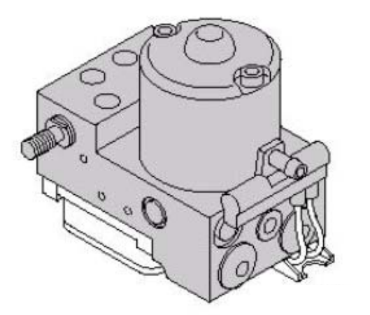
Hydraulic block
It is located on a carrier in the engine compartment. More precisely, the location can be determined by knowing the car model. For example, in the Passat 97, it is located on the driver's side on the shock absorber dome.
Appointment
The hydraulic unit is connected to two brake circuits. In contrast to the outdated ABS, the real hydraulic unit is equipped with additional switching and intake valves. The rotary pump works independently.
Switching valves are:
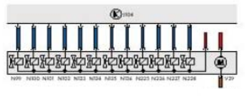
- switching valve –1- dynamics adjustment N225,
- Switch valve -2 - dynamics adjustment N226.
Intake valves are:
- high-pressure switching valve –1- dynamics adjustment N227,
- high-pressure switching valve -2 - adjustment
speakers N228.
A single brake cylinder is controlled with the help of valves in the hydraulic unit.
With the help of intake and exhaust valves, the following system states can be achieved:
- increased pressure in the system,
- maintaining pressure in the system,
- pressure reduction in the system.
Electronic activation
Consequences of failure
In the event of valve failure, the system shuts down.
Diagnostics
Valves N225 and N226, as well as high-pressure valves N227 and N228, are monitored for wiring breaks and short circuits.
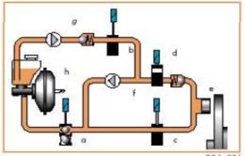
Functional diagram
For ease of understanding, consider the action of one brake circuit and one wheel. The brake circuit consists of:
switch valve N225 (a),
high-pressure valve N227 (b),
intake valve (c),
exhaust valve (d),
brake cylinder (e),
return pump (f),
hydraulic pump dynamics (g),
brake booster (h).
Pressure support
When the ESP kicks in, the hydraulic dynamics pump starts pumping brake fluid into the brake circuit. Thus, brake cylinders and the return pump quickly develop increased brake pressure. The rotary pump further increases brake pressure.
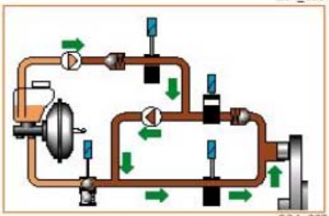
Pressure support
The inlet valve closes. The exhaust valve remains closed. The pressure remains in the cylinders. The rotary pump stops working, Valve N227 closes.
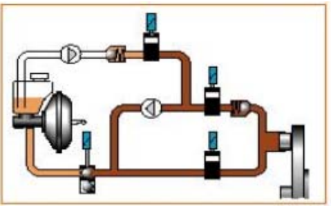
Pressure reduction
Valve N225 begins to act in the opposite direction. The intake valve remains closed, the exhaust valve opens. Brake fluid can return to the reservoir through the master cylinder, thereby reducing the pressure in the brake circuit system.
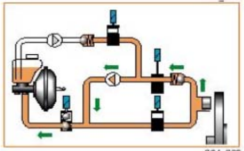
BOSCH functional diagram
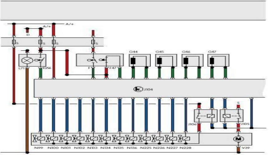
- A/+ Plus food.
- D Ignition on.
- E256 ASR/ESP switch.
- F Brake light switch.
- 47 Brake pedal switch.
- G44 Sensor of the number of revolutions of the right rear wheel.
- G45 Right front wheel speed sensor.
- G46 Sensor of the number of revolutions of the rear left wheel.
- G47 Sensor of the number of revolutions of the front left wheel.
- G85 Angle of rotation sensor.
- G200 Transverse acceleration sensor.
- G201 Brake pressure sensor.
- G202 Steering angle sensor located in the front left footwell, in front of the central comfort control system.
- J104 ABS control unit with EDS/ASR/ESP, in the right front footwell, on the front body wall.
- J105 Rotary pump relay - ABS in the protective casing of the control devices, in the engine compartment at the front right.
- J106 Solenoid valve relay - ABS in the protective casing of the control devices, in the engine compartment at the front right.
- J285 Control device for the display unit in the control panel unit.
- K47 Control lamp ABS.
- K118 Control lamp of the brake system.
- K155 Control lamp ASR/ESP.
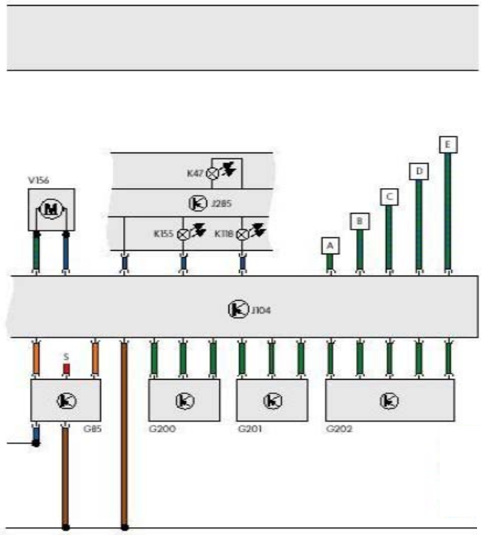
- N99 ABS intake valves front right.
- N100 ABS exhaust valves front right.
- N101 ABS intake valves front left.
- N102 ABS exhaust valves front left.
- N133 ABS intake valves rear right.
- N134 ABS intake valves rear left.
- N135 ABS exhaust valves rear right.
- N136 ABS exhaust valves rear left.
- N225 Switching valve – 1 - dynamic adjustment.
- N226 Switching valve – 2 - dynamic adjustment.
- N227 High-pressure switching valve – 1 - dynamics adjustment.
- N228 High-pressure switching valve – 2 - dynamic adjustment.
- S Fuse.
- V39 ABS rotary pump.
- V156 Hydraulic dynamics adjustment pump.
- A Brake control connection.
- B Navigation system (if available).
- C Engine management.
- D Gearbox control (with automatic transmission).
- E Carrying out diagnostics.
Diagnostics
Diagnostics can be carried out using reading devices VAG 1551, VAG 1551.
- The following functions are at your disposal:
- 00-automatic control,
- 01-request the version of the control device,
- 02-request fault recorder data,
- 04-entering basic settings,
- 05-clear the fault recorder,
- 06-finish issuing data,
- 08-reading the data of the measuring unit,
- 11 - the beginning of the session.
The point of intersection of the ESP and diagnostics systems is the point of entry. The exact location depends on the car model.
Control lamps and diagnostic buttons
If the error occurs during ESP operation, the system will try to complete the operation in optimal mode. After that, the damaged part of the system is turned off, and the emergency signal lights up. Errors are always logged in the error logger. ESP can be disabled using the ASR/ESP switch.
Emergency signals
K118 braking system malfunction control lamp:

Control lamp ABS K47:
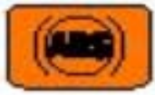
Control lamp ASR/ESP K155:

Overview of the ITT-Automotive system
Components:
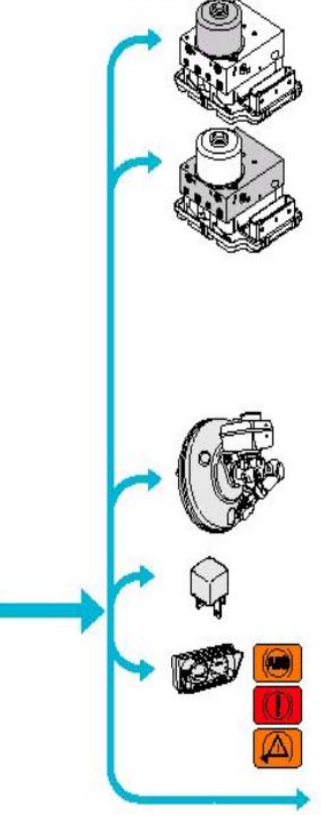
- ABS V64 rotary pump.
- ABS intake valves N99, N101, N133, N134.
- Exhaust valves ABS N100, N102, N135, N136.
- Switching valve -1- adjustment of dynamics N225.
- Switching valve -2- adjustment of dynamics N226.
- High-pressure switching valve -1- dynamics adjustment N227.
- High-pressure switching valve - 2- adjustment of dynamics N228.
- Induction coil N247 in the brake booster.
- J508 brake light cutoff relay on additional carrier above the relay board.
- Control panel display unit J285.
- Control lamp ABS K47.
- K118 braking system malfunction control lamp.
- Control lamp ASR/ESP K155.
- Additional signals.
- Engine management.
- Control of the gearbox.
- Management of the navigation system.
ESP device and functions
System of automatic regulation
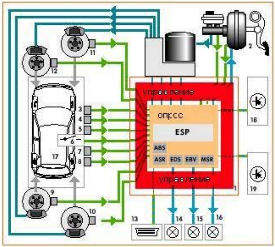
1. Hydraulic unit with ABS control device with EDS/ASR/ESP.
2. Active booster with brake pressure sensor.
3. Longitudinal acceleration sensor (Quattro/Syncro only).
4. Transverse acceleration sensor.
5. Sensor of the angle of rotation.
6. ASR/ESP button.
7. Angle of rotation sensor.
8. Brake light switch.
9-12. Speed sensors.
13. Diagnostic block.
14. Brake system malfunction control lamp.
15. ABS control lamp.
16. Control lamp ASR/ESP.
17. Driver-car mode of operation.
18. Effect on engine management.
19. Influence on the control of the gearbox (only with an automatic gearbox).
The circuit is characterized by how an increase in initial pressure is achieved using an additional brake pressure sensor on the master cylinder. For all-wheel drive cars, a longitudinal acceleration sensor is also added. The role of the hydraulic dynamics pump is taken over by the brake booster using an induction coil and a brake booster brake detection switch. The flow process has already been described: if the given direction of movement and the actual state of the car do not coincide, the system intervenes as long as it is necessary to bring the car to a stable state.
ABS control unit with EDS/ASR/ESP J104
Together with the hydraulic unit, this is a single group, and in terms of the electrical circuit, it is similar to the BOSCH system.
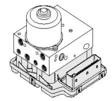
Functions
- Management of ESP, ABS, EDS, ASR, EBV, MSR,
- permanent control over all electronic systems,
- Diagnostic assistance in the service center.
When the ignition is turned on, the control device self-tests. All electrical connections are constantly monitored, the induction coil is periodically tested.
Consequences of failure
In the unlikely event of failure of all components of the control device, the standard braking system without ABS, EBS, ASR and ESP remains at the disposal of the driver.
Automatic inclusion
Control device J104 is polled from the positive connection in the control panel line circuit.
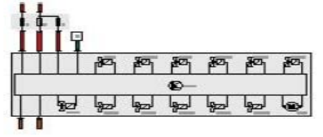
Diagnostics
The following errors are recognized:
- damage to the control device,
- the control device is incorrectly coded,
- power supply errors,
- damage to the hydraulic pump,
- unrecognized ABS signals,
- the data bus mechanism is broken.
Sensor of the angle of rotation G85
It is located in the steering column between the gear shifter and the steering wheel. The turning ring with the contact ring for the driver's airbag is built into the steering angle sensor and is located on the lower part.
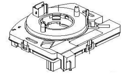
Appointment
The sensor transmits data about the angle of rotation of the steering wheel to the ABS control unit with EDS/ASR/ESP. The perception range is ±720º, which is four full turns of the steering wheel.
Consequences of failure
Without information from this sensor, the desired direction of movement cannot be calculated. The ESP function turns off.
Diagnostics
After replacing the control device or the sensor, the zero position of the sensor must be calibrated:
- no information is received from the angle of rotation sensor;
- wrong setting;
- mechanical error;
- damage;
- implausible signal data.
Electronic activation
The G85 is the only sensor in the ESP system that transmits data directly via the CAN bus to the control unit. After turning on the ignition, the sensor is initiated as soon as the steering wheel turns 4.5º, which corresponds to a turn of about 1.5 cm.
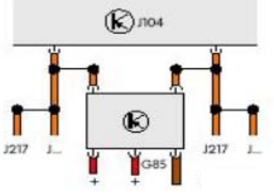
Transverse acceleration sensor G202
According to the laws of physics, this sensor should be as close as possible to the center of gravity of the car. The location and adjustment of the sensor must not be changed in any case. The sensor is located on the right next to the steering column and is fixed on the same board as the steering angle sensor.
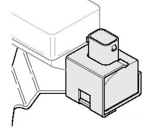
Appointment
The G202 sensor transmits data on the lateral forces acting on the vehicle. At the same time, it provides important data on which the calculation necessary in a real situation to maintain the stability of the car's movements is based.
Consequences of failure
Without information from this sensor, the real position of the car cannot be calculated. The ESP function turns off.
Diagnostics
Diagnostics determines gaps in the connection and the presence of a short circuit. The system also recognizes whether the sensor readings are plausible.
Electronic activation
G200 is connected to the control device J104 by three power lines.
Device
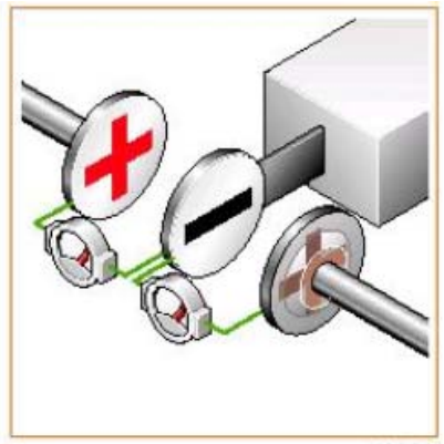
The lateral acceleration sensor works on the capacitive principle. What does it mean? Let's imagine that the sensor consists of two series capacitors. The common middle capacitor plate can move under the influence of any force. Each capacitor has a certain capacity, that is, it can accumulate some electric charge.
Functions
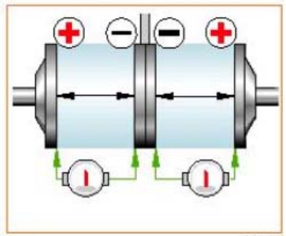
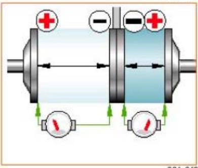
As long as the car does not experience lateral acceleration, the middle plate is equidistant from the outer plates, so the capacity of both capacitors is the same. As soon as the effect of transverse acceleration begins, the middle plate shifts, so that the distance to one of the outer plates becomes smaller, to the other - more. Thus, the capacities of the capacitors change. By changing the capacitance, the electronics calculates the direction and magnitude of the acceleration.
Sensor of the angle of rotation G202
The need for a close location of the center of gravity explains the fact that it is mounted on the same board as the transverse acceleration sensor. Unlike the BOSCH system (the presence of a combined sensor), there are two separate sensors that can be replaced separately.
Appointment
The sensor of the angle of rotation allows you to determine whether the body is acting on a torque. Depending on its location, the sensor can detect rotation around one of the spatial axes. In ESP, the sensor must report the rotation of the car around the vertical axis. The characteristics associated with this concept are: the angle of rotation and the degree of probing.
Electronic connection
The steering angle sensor is connected to the control device J104 by three wires of electrical connection.
Consequences of failure
Without information from this sensor, the ability to turn the car is not calculated. The ESP function turns off.
Diagnostics
Diagnostics determines gaps in the connection and the presence of a short circuit. Also, the system recognizes implausible sensor readings.
Building
The main component is a micromechanical system with a double tuning fork made of monocrystalline silicon, located in a small electronic part on the sensor board. Let's turn to a simplified diagram of a double tuning fork. At the narrowing point, it is connected to the rest of the silicon body, which we will bypass in the description for the sake of clarity. A double tuning fork consists of a tuning fork exciter and a measuring tuning fork.
Functions
The alternating voltage causes the silicon tuning fork to begin to oscillate according to the principle of resonance. Both halves are tuned so that the excitation tuning fork starts oscillating at 11 kHz and the measuring tuning forks at 11.33 kHz. When an alternating voltage of 11 kHz is applied, the exciter tuning fork begins to oscillate, the measuring tuning fork does not. A tuning fork that makes resonant oscillations reacts more inertly to the influence of external mechanical forces on it than at rest. This means that while one part of the tuning fork and the sensor itself, under the influence of the rotating acceleration, moves with the car, the other part does not have time to repeat these movements. Thus, the tuning fork twists like a corkscrew. This rotation affects the charge distribution in the tuning fork, which is measured by electrodes, evaluated by sensor electronics and sent as a signal to the control device.
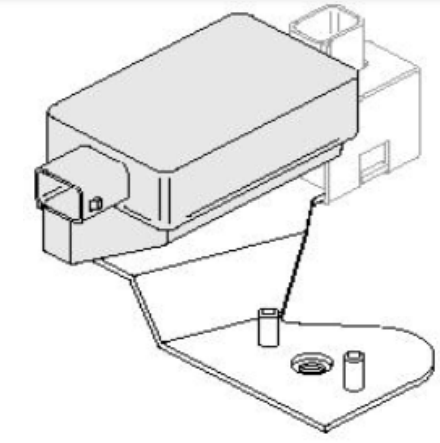
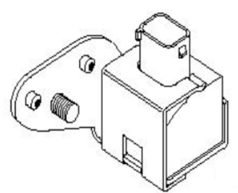
Longitudinal acceleration sensor G249
It is located on the front pillar of the body and is used only in cars with four-wheel drive. In front- or rear-wheel drive cars, longitudinal acceleration is calculated based on the readings of brake pressure sensors, engine speed and other information entering the engine management system. In the presence of all-wheel drive, the front and rear wheels are firmly connected. The calculation of the actual speed of the car may be inaccurate due to the low friction and closed Haldex clutch. The calculated longitudinal acceleration contributes to the refinement of the theoretically calculated speed of the car.
Consequences of failure
Without an additional indicator of longitudinal acceleration, the results of calculating the car's speed may be incorrect. ASR/ESP fail. EBV is active.
Diagnostics
Diagnostics determines gaps in the connection and the presence of a short circuit. Also, the system recognizes implausible sensor readings. You will find the device and functions on page 42. This sensor is deployed at 90° to the lateral acceleration sensor.
Electronic activation
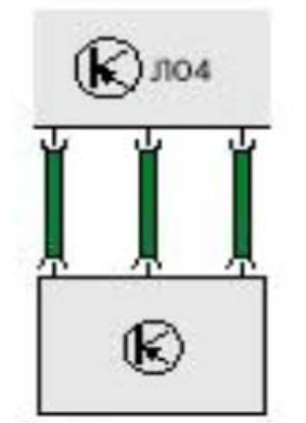
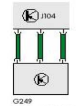
The longitudinal acceleration sensor is connected to the control device by three wires.
Diagnostics
Diagnostics determines gaps in the connection and the presence of a short circuit. Also, the system recognizes implausible sensor readings. You will find the device and functions on page 42. This sensor is deployed at 90° to the lateral acceleration sensor.
ASR/ESP switch E256
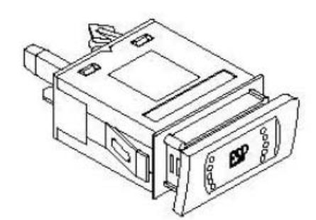
It depends, depending on the car model, on one of the sides of the control panel. The switch allows you to deactivate the ASR/ESP function, which is indicated by the ASR/ESP warning lights. Pressing the button will reactivate the ASR/ESP function. If the driver forgets to turn the system back on, it updates and starts when the engine is started.
Disabling the ESP function is advisable:
• When shaking on deep snow or loose ground.
• When driving with anti-skid chains.
• During the operation of the car on the test bench.
When ESP is active or when the transmission is engaged, this function cannot be disabled.
Consequences of failure
ESP cannot be turned off if the button is damaged.
Diagnostics
An error in operation is not recognized by the diagnostic system.
Active brake booster with master cylinder
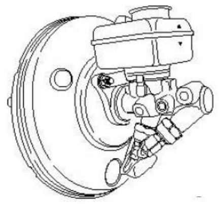
A modified active brake booster or booster is different from older models. In addition to the traditional function of increasing the pressure exerted by the driver's foot on the brake pedal with the additional pressure of the pump or suction pipe, it solves the task of increasing the initial pressure before the ESP action begins. This is necessary because the force of the return pump is sometimes not enough to create the required pressure. The reason for this is the high level of brake fluid viscosity at low temperatures
Advantages of an active brake booster
- its installation does not require special additional efforts.
Consequences of failure
If the induction coils or switch F83 is turned off, this ESP function cannot be engaged.
Diagnostics
The following errors are recognized:
- a break in the wiring,
- short circuits and damaged parts.
Device
Consider a brief description of the device. The booster consists of a modified cylinder (a) and a brake booster (b). The brake booster, in turn, consists of a lower part (c) and a pressure part (d), separated by a membrane. In addition, the amplifier has a magnetic block of valves. The piston valve block is electrically connected to the ESP system.
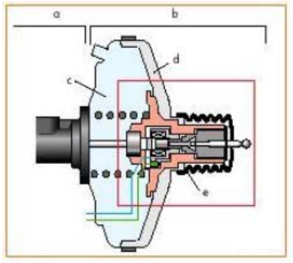
It consists of:
- ESP F83 braking recognition switch,
- induction coil N247,
- various air access valves, which we will not describe in detail here.
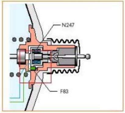
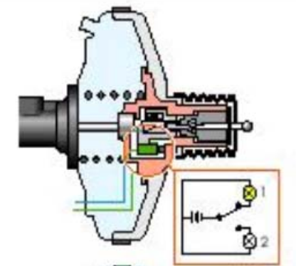
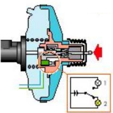
The ESP braking recognition switch is essentially a so-called toggle switch. If the brake pedal is not engaged, the middle contact interacts with signal contact 1, if engaged, contact 2 is closed. Since one contact is always closed, the switch signal is always unambiguous. Which ensures a high level of security.
Block of piston valves
With the help of this unit, an initial pressure of 10 bar is achieved, which is necessary for the return pump to operate regardless of the driver's influence on the brake pedal. When the system recognizes that braking is required and the driver has not yet pressed the brake pedal, the brake pressure induction coil of the ABS/EDS/ASR/ESP control unit is activated. In the induction coil, a magnetic field is created, which draws the metal core into the coil. The valves open, sufficient air is directed into the booster, creating an initial pressure of 10 bar.
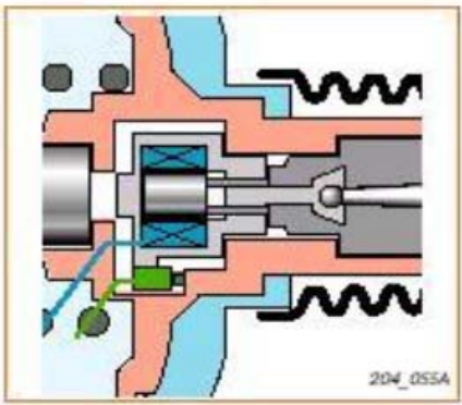
If the initial pressure exceeds the specified, the air access to the inductor coil should be reduced. The metal core slips again, the initial pressure decreases. At the end of the ESP intervention or when the driver presses the brake, the control device deactivates the magnetic coil.
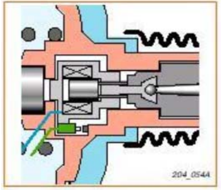
Functioning of the ESP braking detection switch
The brake detection switch sends information to the ESP system that the driver has started to brake. If in the switch the middle contact is in the zone of signal contact 1, the system assumes that it must provide the necessary initial pressure.
If the driver presses the brake pedal, the induction coil moves towards the master cylinder. The middle contact in the switch moves to the zone of signal contact 2 and the system detects braking. The initial pressure in this case is increased by the brake pedal, and therefore the induction coil remains idle.
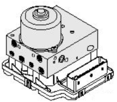
Hydraulic block
It is located on a special carrier in the engine compartment. More precisely, the location depends on the car model.
Device
The hydraulic unit works in series with two brake circuits. Compared to the old ABS units, the new one has been expanded to include one shift valve and a suction valve per brake circuit.
The hydraulic unit has the following switching valves:
Switch valve –1- adjustment of dynamics N225,
Switching valve -2- adjustment of dynamics N226.
The hydraulic unit has the following high-pressure switching valves:
- High-pressure switching valve - 1- dynamics adjustment N227,
- High-pressure switching valve - 2- adjustment of dynamics N228.
There are three system positions:
- Pressure increase,
- pressure support,
- Pressure reduction.
Consequences of failure
If the operation of the valves deviates from the set mode, the system is turned off.
Diagnostics
All valves and pumps are constantly monitored by electronics. In case of errors in electronics.
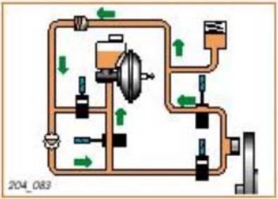
Functional diagram
For simplicity, consider one wheel of the braking circuit. Its components are:
- Switch valve N225(a),
- High-pressure valve N227 (b),
- Intake valve (c),
- Exhaust valve (d),
- Wheel brake cylinder (e),
- Rotary pump (f), active
- brake booster (h).
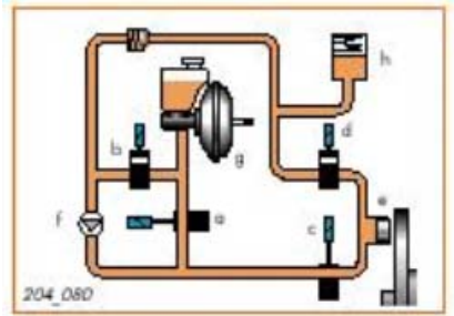
Pressure increase
The booster increases the initial pressure to ensure suction of the brake fluid. N225 – closed, N227 – open. The intake valve remains open until the wheel brakes.
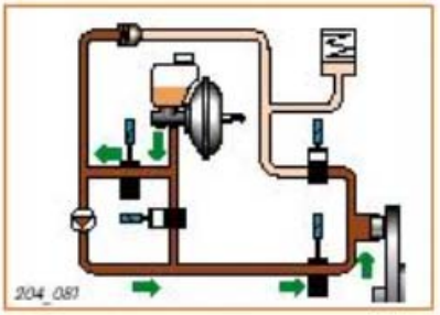
Pressure support
All valves are closed
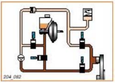
Pressure reduction
Outlet valve open, valve N225 open or closed depending on desired pressure. Valve N227 and intake valve are open. Brake fluid N225 is sent to the initial reservoir, thereby reducing the pressure in the hydraulic unit.
Functional diagram of ITT-Automotive
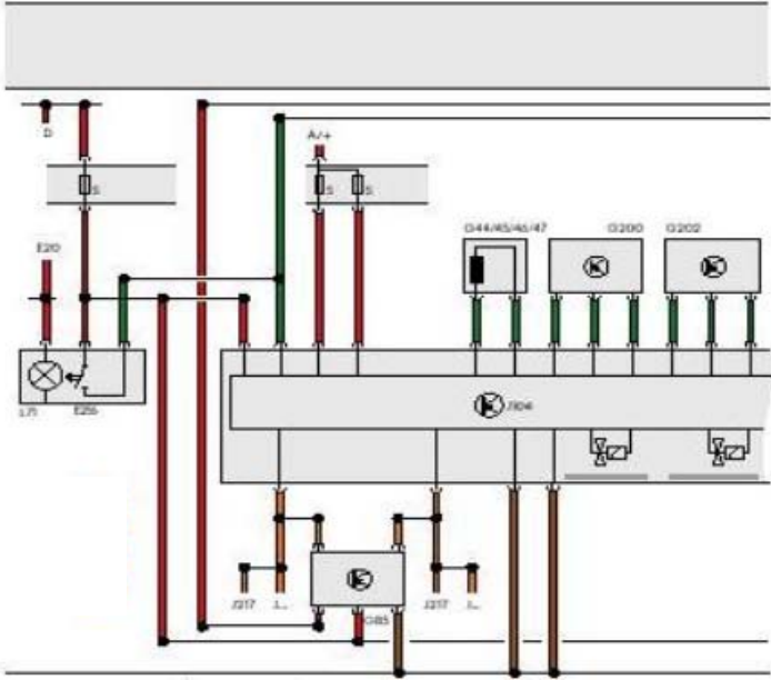
- A/+ - Plus system power.
- D - Turn on the ignition.
- E20 - Control panel lighting regulator.
- E256 - ASR/ESP button.
- F - Brake light switch.
- F9 - Handbrake switch.
- F34 - Low brake fluid warning.
- F47 - Brake pedal switch.
- F83 - ESP braking detection switch in the brake booster.
- G44-47 - Speed sensors.
- G85 - Angle of rotation sensor.
- G200 - Transverse acceleration sensor.
- G201 - Brake pressure sensor -1- on the master cylinder.
- G202 - Sensor of the angle of rotation, in the footwell at the front left, in front of the central control system of the comfort system.
- G214 - Brake pressure sensor -2- on the master cylinder.
- G249 - Longitudinal acceleration sensor, on the right in the front pillar of the body.
- J - Control devices of the engine management system.
- J 104 - ABS control unit with EDS/ASR/ESP - in the front right footwell, on the front body wall.
- J217 - Automatic transmission control unit, next to the radiator barrel.
- J285 - Device for controlling the display unit.
- J401 - Navigation system control device with CD player.
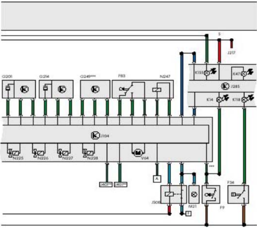
- J508 Brake light off relay on optional carrier above relay board.
- K14 Handbrake control lamp.
- K47 Control lamp ABS.
- K118 Brake system malfunction control lamp.
- K155 Control lamp ASR/ESP.
- L71 Switch illumination/ASR.
- M21 Brake light and reverse light bulb.
- N225 Switching valve –1- dynamics adjustment.
- N226 Switching valve –2- dynamics adjustment.
- N227 High-pressure switching valve -1- dynamics adjustment.
- N228 High-pressure switching valve -2- dynamics adjustment.
- N247 Induction coil with brake booster.
- S Fuse.
- V64 ABS rotary pump.
- A Conducting diagnostics.
* only with automatic transmission
** only if there is a navigation system
*** only with four-wheel drive.
Diagnostics
Diagnostics is carried out using VAG 1551 and VAG 1552 devices. The following functions and capabilities are at your disposal:
- 00-automatic control,
- 01-request the version of the control device,
- 02-request fault recorder data,
- 03-diagnosis of a separate part,
- 04-entering basic settings,
- 05- clear the fault recorder,
- 06-finish issuing data,
- 08-reading the data of the measuring unit,
- 11-beginning of the session.
The point of intersection of the ESP and diagnostics systems is the point of entry. The exact location depends on the car model.
Errors in the operation of the speed sensor
If at least one speed sensor fails, the ABS and ASR/ESP warning lights are turned on, and the corresponding systems are disabled. The EBV function remains available. If the malfunction does not appear both during self-testing and at a speed of more than 20 km/h, the control lamps are turned off.
Features
- Function 04 "Entering basic settings" includes the following options:
- 60 - zero setting for the angle of rotation sensor
- 63- zero setting for the transverse acceleration sensor
- 66 - zero setting for brake pressure sensors
- 69 - zero setting for the longitudinal acceleration sensor (only with four-wheel drive).
The "zero setting" option is necessary in the event that component parts are replaced. You will find a detailed description in the "Golf 1998" repair manual, "Diagnostics of ABS systems: EDS, MSR, ASR, ESP".
Errors in the operation of the speed sensor
If at least one speed sensor fails, the ABS and ASR/ESP warning lights are turned on, and the corresponding systems are disabled. The EBV function remains available. If the malfunction does not appear both during self-testing and at a speed of more than 20 km/h, the control lamps are turned off.
Warning signals and diagnostic sensors
If an ESP malfunction occurs during its operation, the system tries to complete the operation in the optimal mode. After that, the damaged part of the system is turned off, and the emergency signal lights up. Errors are always logged in the error logger. The ESP function can be disabled using the ASR/ESP button.
K118 braking system malfunction control lamp:

Control lamp ABS K47:
Control lamp ASR/ESP K155:

SERVICE
Consider that in some cases, such as tachometer or lateral acceleration sensors, these are ultra-sensitive measuring instruments originally designed as space engineering.
Ago:
• parts should be transported in the original packaging, unpacked only immediately before installation,
• do not miss details,
• do not place heavy objects on the sensors,
• mount in the designated place,
• follow hygienic regulations for the workplace.
Calibration of sensors and sensors
After replacing the steering wheel angle sensor G85 or control unit J104, the new sensor must be calibrated. This means that the sensor must "understand" what position of the steering wheel is considered normal for straight-line movement. You will find a detailed description of the process in the corresponding reference literature. Please note that the yellow dot on the sight glass on the underside of the steering wheel angle sensor must be fully visible. This indicates that the sensor is at a zero angle. After replacing the pressure, lateral acceleration and longitudinal acceleration sensors, they must also be calibrated using the VAG 1551 and VAG 1552 flaw detectors. The adjustment of the speed sensor is automatic.