Engine AGR 1.9 l TDI

AvtoAd
02/12/2022
For the first time in the OCTAVIA, Skoda offers a modern turbodiesel with direct injection. This engine has an intelligent engine management system that ensures high power and low fuel consumption.
Content
4. A brief description of the mechanical components of the TDI.
13. Overview of the TDI electronic control system.
14. Accelerator pedal position sensor G79.
17. Pressure sensor in the intake manifold G71 and temperature sensor in the intake manifold G72.
18. Modulating piston movement sensor G149.
19. Fuel temperature sensor G81.
20. Coolant temperature sensor G62.
22. Brake pedal switches for F and F47 direct injection diesel systems.
24. Terminal DF of the generator.
25. Air conditioner (contact 48).
29. Glow period and signal lamp K29.
30. Heating elements of the Q7 cooling system.
31. Glow plugs of the Q6 engine.
33. The beginning of the injection valve N108.
34. Solenoid valve for adjustment of boost pressure N75.
35. Exhaust gas recirculation valve N18.
36. Fuel consumption (contact 18).
37. Control of fuel measurement.
38. Exhaust gas recirculation.
Technical data
Engine code: AGR.
Type: 4-cylinder in-line turbodiesel.
Working volume: 1896 cm3.
Hole diameter: 79.5 mm.
Stroke: 95.5 mm.
Compression ratio: 19.5:1.
Nominal power: 66 kW (90 h) at 4000 rpm.
Max. torque: 202 Nm at 1900 rpm.
Mixture formation: Direct injection using an electronically controlled distribution pump.
Emission control: exhaust gas recirculation and oxidation catalytic converter.
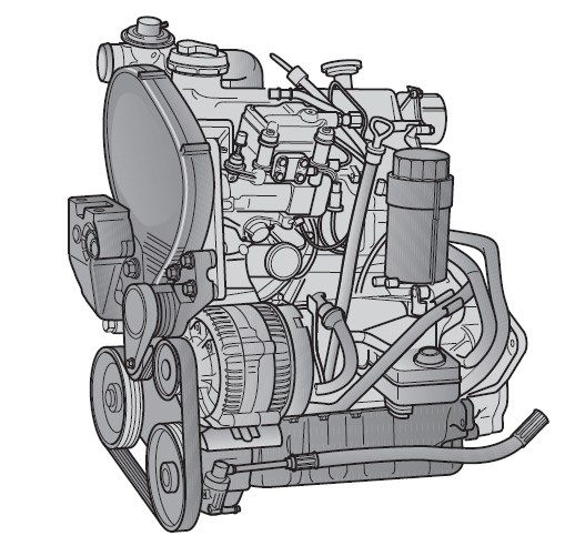
1.9-l. The TDI engine reaches a maximum output of 66 kW (90 hp) at 4,000 rpm. The engine is characterized by a particularly good torque curve. The maximum torque of 202 Nm is available already at 1900 rpm. These engine data reflect the excellent pulling power of the engine.
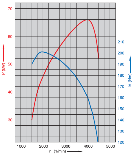
P = output
M = torque
N = engine speed
TDI engine
Features of the engine
- Distribution pump Bosch VP 37 EDC with 800 bar pump pressure. The injection pump distributor is a preliminary setting. The flange is pressed onto the drive shaft and cannot be removed.
- The inlet port is designed as a vortex port. Sets the introduced air in a vortex motion, which ensures intensive swirling of the air in the combustion chamber.
- Piston cup of a special shape (main combustion chamber).
- Injectors with two-stage fuel injection.
- Charge pressure control.
- The coolant pump is installed in the cylinder block.
- Coolant thermostat installed in the cylinder block.
- The coolant is preheated by an auxiliary electric heater.
- Free running of the generator.
- Exhaust gas recirculation valve in the intake manifold.
- Injection pipes with plastic coating as protection against corrosion.
- The valve cover gasket is vulcanized in place.
- Oil pan with silicone sealant.
- Replaceable oil filter in the form of a paper cartridge.
- A vacuum pump with a camshaft drive.
Electronic management
The amount of fuel injected and the injection timing are electronically controlled to meet the high fuel consumption and emissions requirements. This task is performed by the Electronic Diesel Control (EDC).
It determines the amount of fuel and the start of injection of the high pressure distributor, controls the boost pressure, exhaust gas recirculation and the glow period.
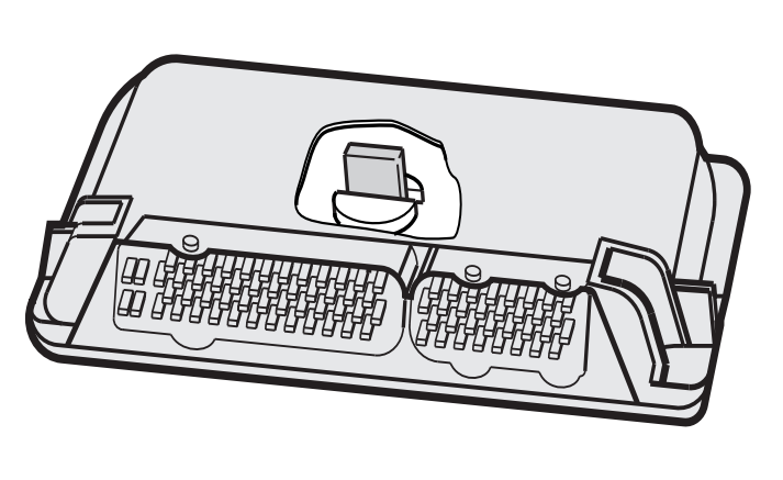
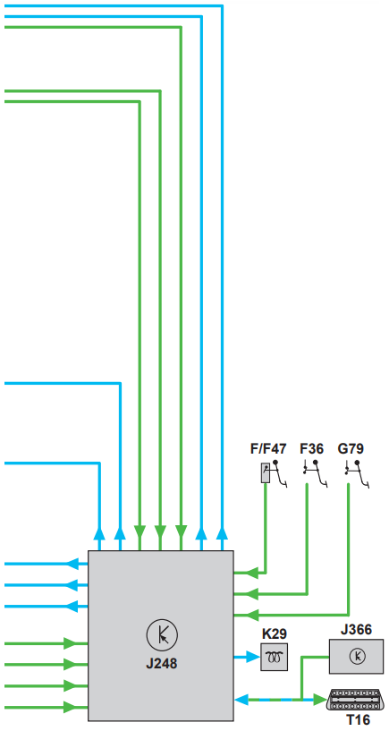
J248 diesel direct injection system control unit.
A brief description of the mechanical components of the TDI
Adjusting the fuel injection distributor and toothed belt
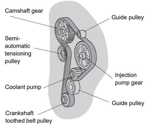
The toothed belt drives:
- Camshaft
- TNVD-distributor
- Coolant pump
The necessary arc of the belt is provided by two guide pulleys, tension by a semi-automatic tensioning pulley of a toothed belt.
Adjusting the toothed belt
Appropriate markings (crankshaft position, camshaft position, fuel injection pump) are provided for adjusting the gas distribution phases.
Position of the crankshaft
The marking - top dead center of cylinder 1 - is visible on the flywheel through the inspection hole of the gearbox.
The position of the camshaft
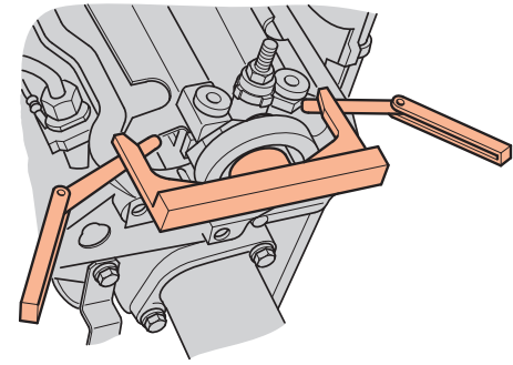
The correct position is fixed by a new setting gauge. The exact middle position should be determined using feelers. The exact position of the camshaft is of great importance for accurate timing when installed on the timing belt.
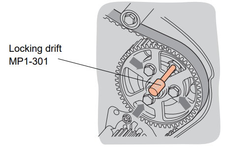
High pressure pump gear
The position of the injection pump is fixed with a punch. The injection pump gear is divided into two parts. Fine adjustment can be made by loosening the 3 bolts (arrows).
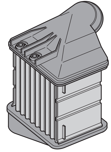
Charge air cooler
The intercooler cools the intake air before it enters the intake manifold. The charge air cooler is installed between the bumper and the right wing and is cooled by the air flow. Why is a charge air cooler needed? The TDI engine's turbocharger heats the intake air, which results in a loss of engine power. This power loss can be avoided by cooling the intake air in the charge air cooler. As air temperature decreases, air density increases. The cylinders are filled with colder and denser air, richer in oxygen, which, in turn, leads to a further increase in engine power.
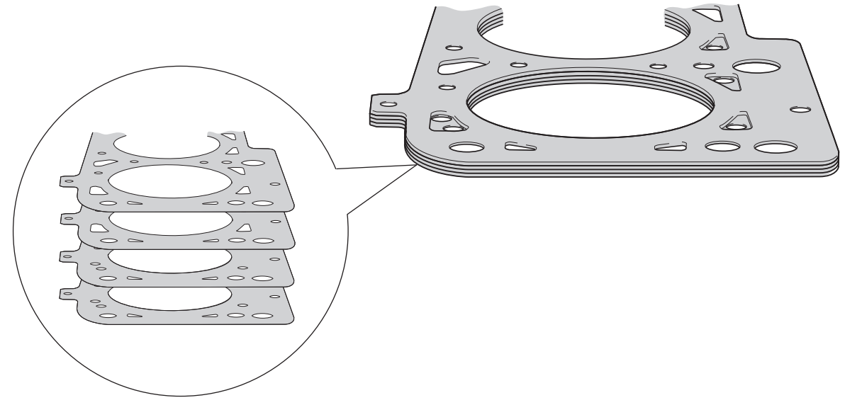
Cylinder head gasket
The cylinder head gasket is made of metal, so it is resistant to high temperatures and pressure. The gasket can also be used in other 1.9-liter engines. range of diesel engines.
Injector nozzles
A moderate increase in pressure in the combustion chamber is necessary to minimize combustion noises and reduce mechanical loads. In addition, fuel should not be injected suddenly, but continuously over a long period of time. This injector injects fuel in two stages.
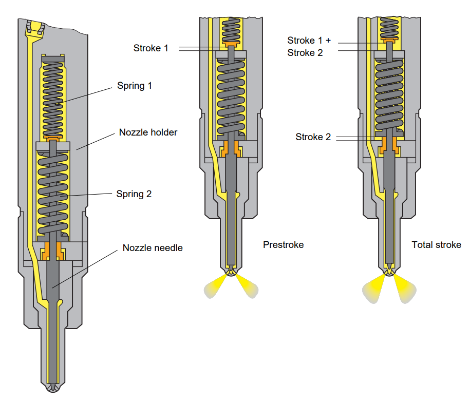
Function
- 1st stage (post-impact moment)
The nozzle holder contains two springs of different thickness. They are adjusted to each other in such a way that the injector needle rises only against the force of spring 1 at the start of injection. As a result of the gap created in stroke 1, only a small amount of fuel is pre-injected at low pressure (p = 190 bar).
This leads to a moderate increase in the combustion pressure and creates the conditions necessary for the ignition of the main amount of fuel.
- 2nd stage (general impact)
The injection pump constantly supplies more fuel. This results in increased pressure in the injection nozzle because the amount of fuel supplied by the pump cannot escape through the small gap. As a result of this increase in pressure, the force of the spring 2 is overcome and the needle of the nozzle rises by stroke 2 to full stroke. Due to the increased gap, the main injection of the remaining fuel occurs at a higher injection pressure (p = 300 bar).
Needle lift sensor G80
The injection nozzle of the 3rd cylinder is equipped with a G80 needle lift sensor to determine the start of injection. The sender monitors the actual opening moment of the injector nozzle, and the signal is transmitted to the EDC control unit. The electronic control unit compares the input signal with the injection start map and analyzes the difference.
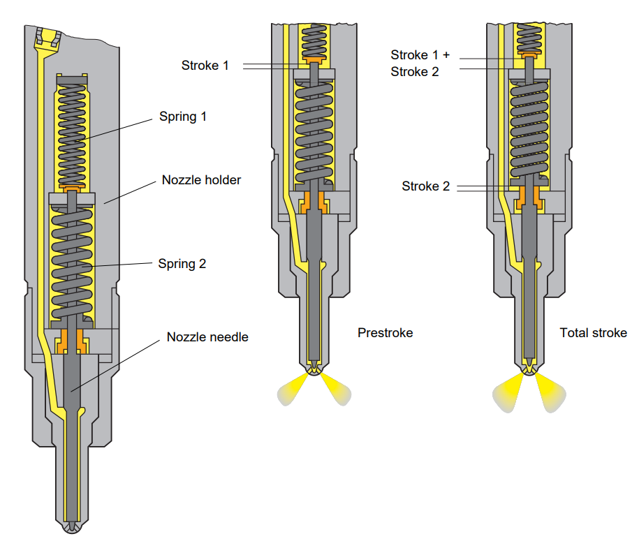
Function
- The G80 needle lift sensor consists of a magnetic coil that is supplied with direct current from the control unit. This current creates a magnetic field in the coil.
- The stop pin is located in the inner part of the magnetic coil as an extension of the nozzle needle. The movement of the stop pin causes a change in the induced voltage in the magnetic coil.
- The voltage induction moment in the coil is compared by the control unit with the top dead center signal. The actual start of injection is calculated from this difference. The "actual" injection start value is then compared to the "set" value and the injection start is adjusted accordingly if there are differences.
Substitution function
If the needle lift sensor fails, the emergency program is activated. The start of injection is controlled by this program based on the stored injection map. In addition, the amount of fuel injected is reduced.
Backflow restrictor
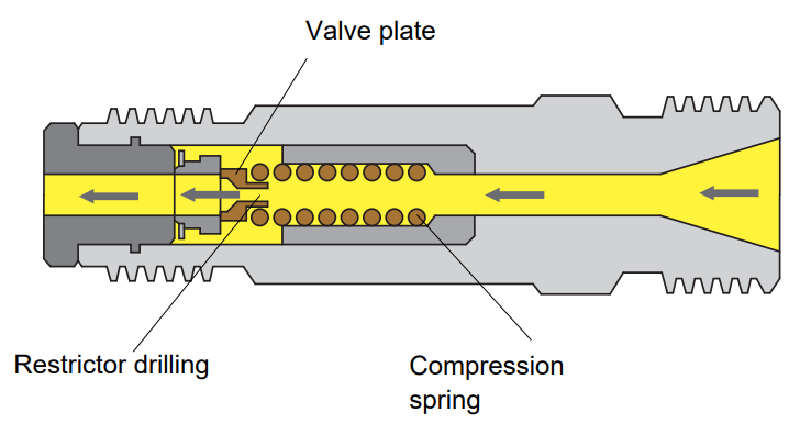
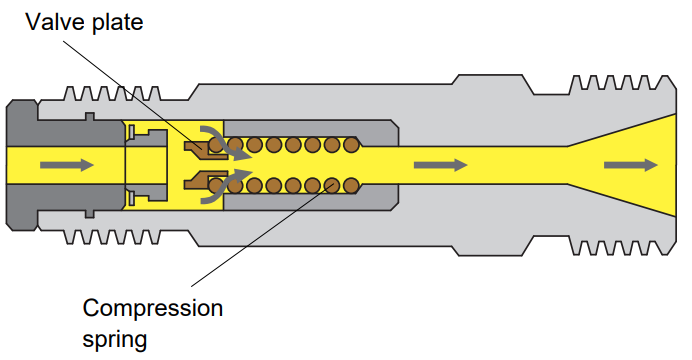
The backflow restrictor is located in the pressure valve of the injection pump, which controls the flow in the injection pipe to the pump. The purpose of the backflow restrictor is to prevent further fuel leakage from the injector nozzle and the formation of vapor bubbles in the injector tube.
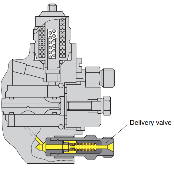
Reverse flow
During the return flow, the force of the pressure spring acts on it and blocks the main passage. Fuel enters only through the drilling of the limiter. This dampens any pressure wave that may exist.
Delivery of fuel
During fuel supply, the valve plate rises under the influence of fuel pressure, and the restrictor drill does not work. Fuel enters through the main channel.
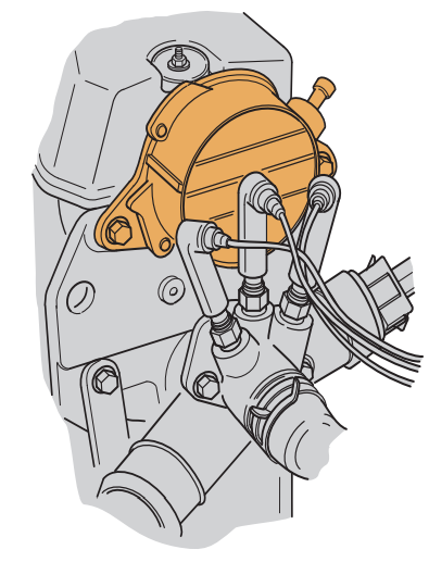
Vacuum pump
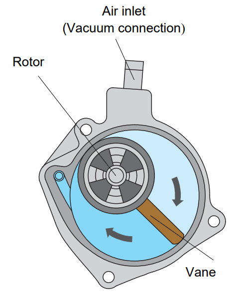
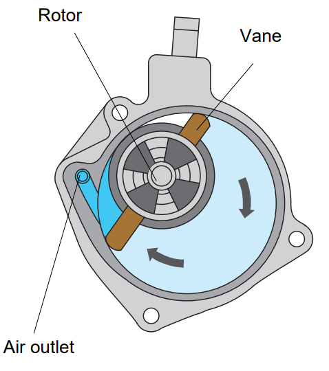
The vacuum pump, which is additionally required on a diesel engine to create a vacuum, is driven directly by the camshaft. A vacuum pump consists of a rotor and a vane. The blade is made of plastic and can be moved on its mounts.
Expansion of space
During the rotational movement of the rotor, the blade is pushed outward and the space expands. The space is filled with air, as a result of which a vacuum is formed at the air inlet. The vacuum created in the pump is used by the brake servo and the EGR valve.
Contraction of space
As the rotor and blade continue to rotate, the resulting space shrinks again. As a result, the injected air is compressed and blown through the air outlet into the cylinder head. At the same time, space is formed again from above.
System architecture
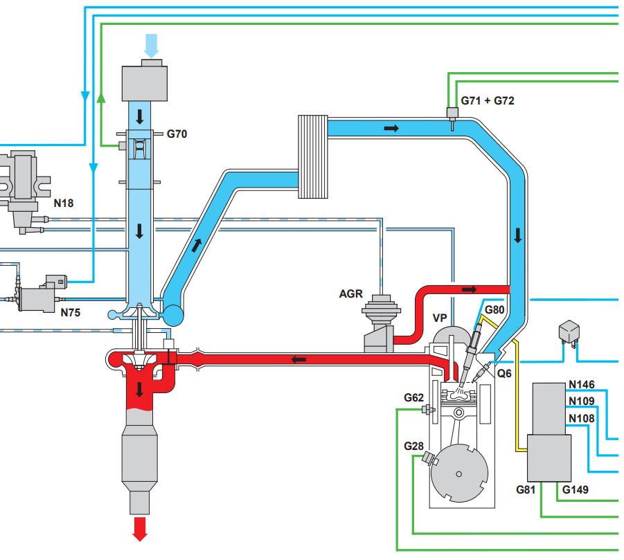
1.9-l. The TDI engine is equipped with an electronic engine control unit. All engine control systems are combined into a control unit.
With electronic fuel injection control, the amount of fuel injected can be adjusted according to air pressure, air temperature, coolant temperature and fuel temperature. In the past, using mechanical control systems, it was impossible to take these parameters into account.
The use of an electronic control unit makes it possible to achieve such demanding goals as reducing fuel consumption and pollutant emissions, while ensuring a high degree of accuracy over time. At the same time, the system is able to respond more quickly to the loads that may occur with higher engine power.
Control functions
Control of the entered quantity
- Calculation of the amount of fuel for injection from performance curves
- Start quantity control
- Fuel cut-off when exceeding
- Limiting the quantity injected if black exhaust is produced
- Control of idling speed and limit speed of the engine
- Controlling the amount of injection to improve the smoothness of the stroke
Advance injection
- Basic injection start setting according to injection maps
- Correction in the warm-up phase
- Engine injection moment control has started
EGR exhaust gas recirculation
Map driven
Charge limit pressure
- Charge pressure map control
- Controlled according to the working condition
Additional coolant heater
Card control of heating
Glow period
- Glow period monitoring map
- Afterglow
Self-diagnosis
- Monitoring of sensors and actuators
- Fault memory
- Basic setting
- Diagnostics of executive mechanisms
- Emergency functions
- Reading the measurement results using the VAG 1551 fault reader or the VAG 1552 vehicle system tester.
The maintenance of the engine is greatly simplified and the number of operations required during the inspection is reduced due to the fact that there is no need to adjust the injection pump.
Any malfunctions that occur can be quickly detected and easily eliminated thanks to a complete self-diagnosis system.
Location of components
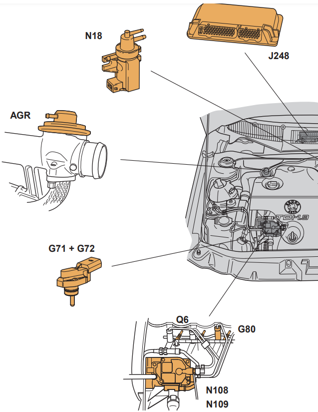
EGR EGR valve
G71 Pressure sensor in the intake manifold
G72 Intake manifold temperature sensor
G80 Needle lift sensor
J248 Control unit
EDC EGR valve N18
N108 Injector valve start
N109 Fuel shut-off valve
Q6 Glow plugs (engine)
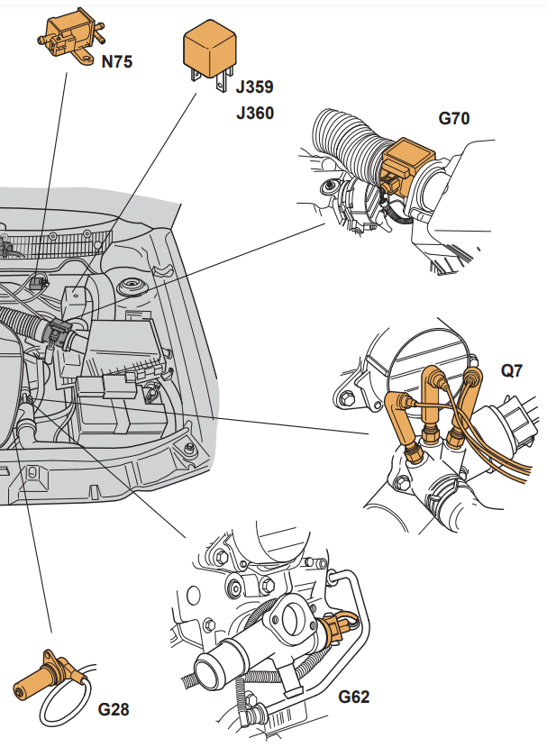
G28 Engine speed sensor
G62 Coolant temperature sensor
G70 Air mass meter
J359 Low power heating relay
J360 High power heating relay
N75 Charge pressure control solenoid valve
Q7 Heating elements (coolant)
Overview of the TDI electronic control system
The J248 direct injection diesel control unit uses maps and characteristic curves to ensure optimum engine performance in terms of torque development, fuel consumption and emission characteristics in any operating situation.
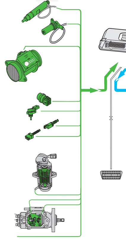
Sensors
- Needle lift sensor G80
- Engine speed sensor G28
- Coolant temperature sensor G62
- Air mass meter G70
- G72 intake manifold temperature sensor
- + G71 intake manifold pressure sensor
- Stop light/brake pedal switch F/F47
- Clutch pedal switch F36
- Accelerator pedal position sensor G79
- + Idle switch F60
- + Kickdown switch F8
- Regulating piston movement sensor G149
- Fuel temperature sensor G81
- Additional signals
Sensors
• Air conditioner
• Terminal DF
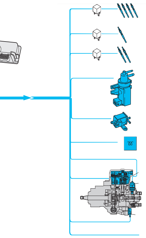
Actuators
- Glow plugs (engine) Q6
- Glow plug relay J52
- Heating element (cooler) Q7
- Relay of low thermal capacity J359
- TENs (heat carrier) Q7
- Relay of high thermal capacity J360
- EGR valve N18
- Solenoid valve for regulating boost pressure N75
- Glow period indicator K29
- Quantity regulator N146
- Fuel shut-off valve N109
- Start of injection valve N108
Additional signals:
• Engine speed signal
• Fuel consumption signal
• Air conditioner
Accelerator pedal position sensor G79
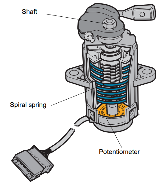
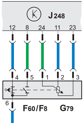
The determining factor for calculating the required amount of fuel for injection is the position of the accelerator pedal - the driver's input. This is detected by the sender. The accelerator pedal position sensor G79 is a potentiometer that is installed in the pedal mount. Operated by a short cable. The potentiometer transmits the corresponding angle of rotation to the electronic control unit. A coil spring in the sensor housing creates a restoring force that gives the driver the impression that he is operating a mechanical accelerator pedal. In addition to the potentiometer, the sensor also contains an F60 idle switch and an F8 kickdown switch.
Signal analysis
The electronic control unit calculates the amount of fuel to be injected and the start of injection based on the signal provided by the sensor. In addition, these signals are used to control boost pressure and to operate the exhaust gas recirculation system.
Substitution function
If the sensor is faulty, the engine runs at a high idle speed of about 1300 rpm. Thus, the client can drive to the nearest workshop. In this case, the accelerator pedal position sensor G79 does not work.
Self-diagnosis
The fact that the sender's signal is implausible is stored in the electronic control unit. This signal can be checked in function "08", reading unit of measured values, display group "002". The value of the position of the accelerator pedal is displayed in the second field of the display in the form of %.
Engine speed sensor G28
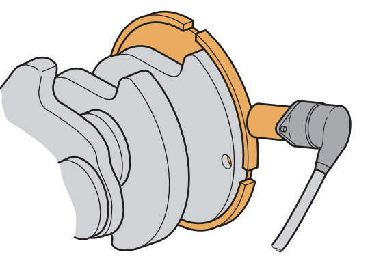
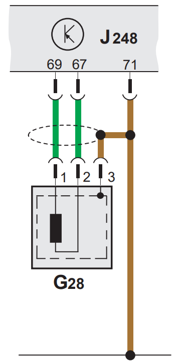
Engine speed is one of the most important parameters for calculating the amount of fuel to be injected and when to start the injection. The inductive engine speed sensor G28 monitors the angular position of the crankshaft. A transmission rotor (a disc with four grooves) is installed on the crankshaft. The correct position is fixed with a dowel-pin. The distance between two consecutive pulses is measured in the electronic control unit. The instantaneous value of the crankshaft position is calculated by analyzing four pulses.
Signal analysis
The signal is used to calculate the amount of fuel to inject and start the injection. The signal from the engine speed sensor is analyzed to perform the functions of exhaust gas recirculation, glow plug preheating and a signal for the glow period indicator lamp.
Substitution function
If the engine speed sensor fails, the electronic control unit switches to emergency mode. The signal provided by the needle lift sensor G80 is used as a substitute signal. The start of the injection is controlled according to the injection maps, while the boost pressure and the amount of fuel injected are reduced. Idle control, fuel cut-off when coasting and air conditioning are turned off, as a result of which the engine speed is slightly reduced during braking. In general, this malfunction is noticeable by an increase in idle speed.
Self-diagnosis
Two possible causes of malfunctions are stored in the electronic control unit:
- The signal is implausible
- No signal
Air mass meter G70
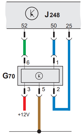
The task of the air mass meter is to determine the mass of fresh air supplied to the engine. The air mass meter G70 is installed in the intake manifold directly behind the air filter. It measures the induction mass of the air using a hot film sensor. The hot film is heated by a voltage of 12 V. The induction air flowing past cools the surface of the hot film. As a result of surface cooling, the resistance of the hot film decreases. The voltage drop caused by this change in resistance is analyzed by the electronic controller as equivalent to the temperature and mass of the input air.
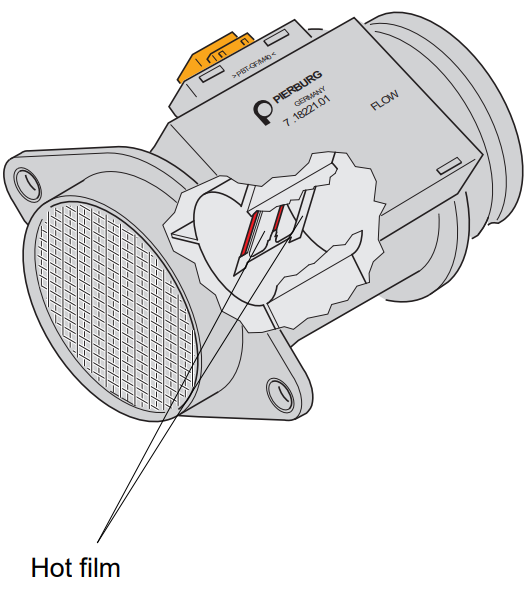
Signal analysis
The measurement result obtained by the air mass meter is used to control the percentage addition of mass of recirculated exhaust gas and the maximum amount of fuel to be injected. A smoke map stored in the control unit limits the amount of injected air if the injected air is insufficient for clean combustion.
Substitution function
If the air mass meter fails, the boost pressure limit is lowered and fixed values are set to ensure optimum engine performance in the part throttle range. This leads to a decrease in engine power.
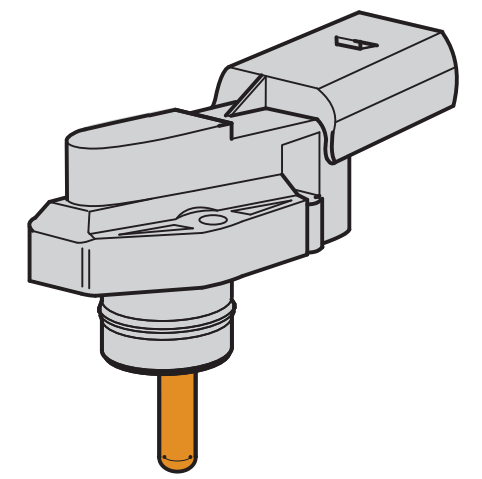
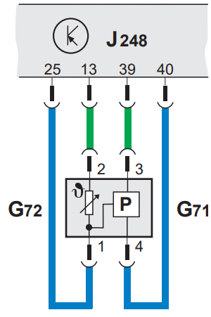
G71 intake manifold pressure sensor and G72 intake manifold temperature sensor
The sensor is located behind the charge air cooler. Its signal provides information about the pressure and temperature of the air in the intake manifold. The boost pressure is additionally adjusted by the value of pressure and temperature in the intake manifold.
Signal analysis
The signals from sensors G71/G72 are used to limit the charge pressure and to control the auxiliary heater.
Substitution function
If the G71 sensor fails, the electronic control unit sets a fixed value. This fixed value maintains charge pressure control. If the G72 sensor fails, the electronic control unit will indicate a value of approximately 20°C to calculate the charge limit pressure and for the auxiliary heater function.
Self-diagnosis
The control unit stores two possible malfunctions:
– Short circuit to ground
– Open/short circuit
Modulating piston movement sensor G149
The modulated piston movement sensor G149 monitors the angle of rotation of the eccentric shaft of the fuel metering control system in the injection pump. This is a contactless sensor. Its signals are transmitted directly to the electronic control unit. The sensor consists of two inductive sensors, the principle of operation of which is based on the principle of a differential transformer. The use of non-contact sensors ensures that the sender works properly regardless of the environment, so that any water that may be present in the fuel does not give any falsified results. An alternating magnetic field is created along a specially shaped iron core using an alternating voltage. A movable iron ring is attached to the eccentric shaft and can move along the iron core. The alternating magnetic field changes according to the position of the moving iron ring. This results in induction and alternating voltage in the coil. The phase shift of the induced voltage relative to the set voltage is taken as a measure of the position of the fuel metering regulator. Temperature effects can be ignored because both voltages originate from the same sender and are transmitted through the same wiring system.
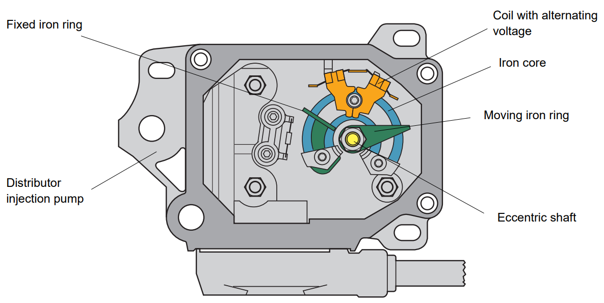
Signal analysis
The sender's signal corresponds to the instantaneous position of the fuel metering regulator. It is used to compare the "actual position" of the fuel metering regulator with the position calculated by the electronic control unit. If a difference between the set and actual positions is detected, the quantity regulator N146 changes the position of the fuel metering regulator accordingly.
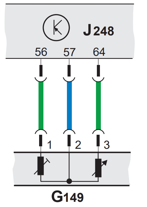
Substitution function
If the control unit does not receive a signal from the piston movement sensor G149, the engine stops for safety.
Fuel temperature sensor G81
The fuel temperature sensor measures the fuel temperature in the injection pump. The measurement result is displayed as a voltage change on the electronic control unit. The temperature of the fuel is a very important factor, because the density of the fuel directly depends on its temperature. Fuel under high pressure is pumped through the injector nozzles by a small high-pressure pump piston. The fuel temperature must be known to accurately calculate the injection quantity and injection start. Correct values can be calculated from the known relationship between fuel temperature and density.
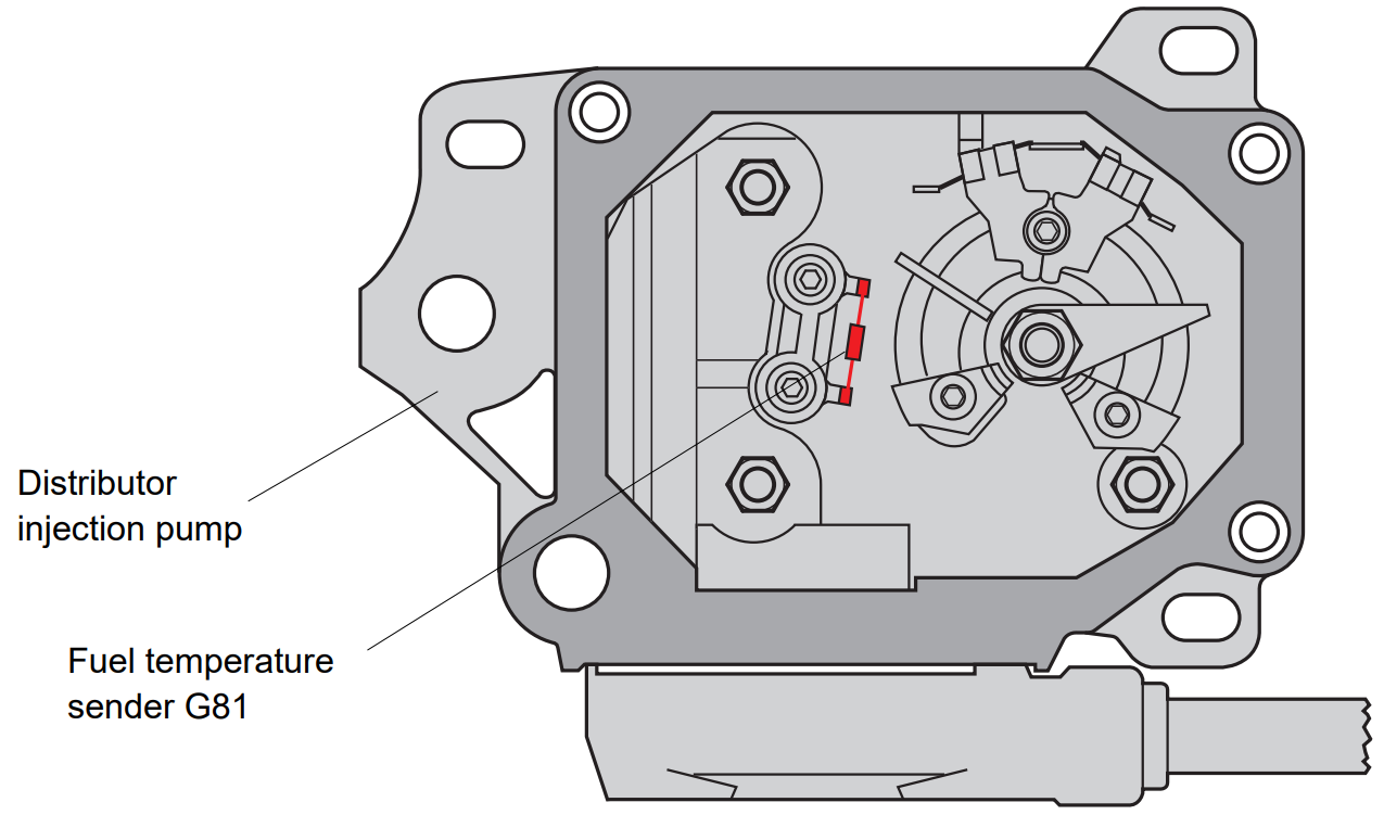
Signal analysis
The amount of fuel to be injected and the injection start time are calculated from the signal provided by the fuel temperature sensor.
Substitution function
If the sender fails, the electronic control unit specifies a fixed value as the basis for the calculation.
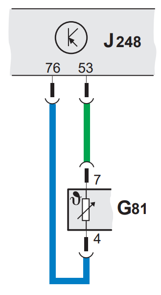
Self-diagnosis
The electronic control stores the following causes of malfunctions:
– Short circuit to ground;
– Open/short circuit.
The fuel temperature is displayed in °C in function "08", reading block of measured values, display group "007", display field "1".
Coolant temperature sensor G62
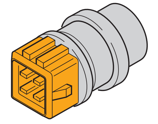
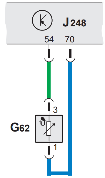
The coolant temperature sensor is located in the coolant nozzle of the cylinder head. The sensor is made in the form of a resistor with a negative temperature coefficient (NTC). As a result of the voltage drop, the instantaneous value of the coolant temperature is transmitted to the electronic control unit.
Signal analysis
The coolant temperature signal is taken into account when calculating the amount of fuel to be injected, the start of the injection, the glow period, the amount of exhaust gas recirculation and to control the auxiliary heater system.
Substitution function
If there is an error in the signal, the fuel temperature is used as a substitute signal. The maximum possible time is used for the glow period. Auxiliary heater is off.
Self-diagnosis
The following possible causes of malfunctions are stored:
- Short circuit to ground;
- Open/short circuit.
The temperature of the heat carrier is displayed in °C in function "08", unit for reading measured values, display group "007", display field 4.
Height sensor F96
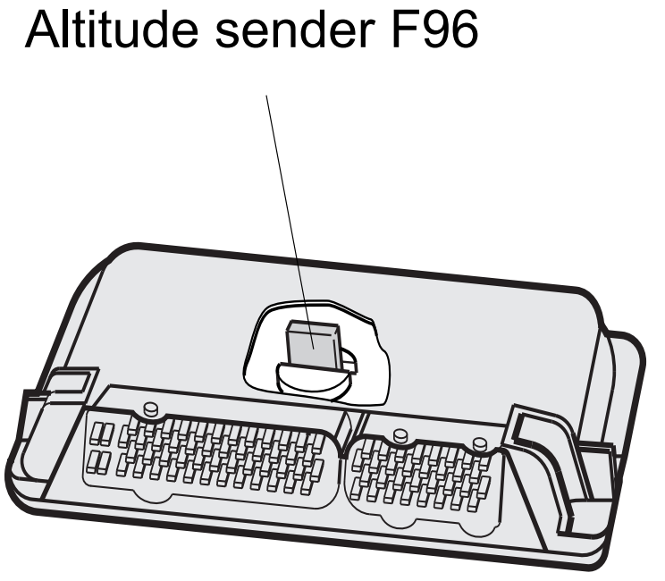
The height sensor is integrated into the J248 diesel direct injection control unit. Measurement is carried out directly in the control unit. The height sensor contains a piezoceramic element. When a force is applied to the piezo crystal, it releases a voltage. This voltage is a measure of air pressure. Air pressure, in turn, depends on geographic altitude, in other words, air pressure decreases with increasing altitude. Boost pressure and exhaust gas recirculation are reduced if there is a drop in air pressure to avoid black exhaust.
Signal analysis
The electronic control calculates the limit pressure of the charge based on the signal provided by the altitude sensor.
Substitution function
If the altitude sensor fails, the charge pressure is controlled according to a fixed value.
Self-diagnosis
The electronic control unit stores any malfunctions that occur. Air pressure is displayed in mbar in function "08", reading block of measured values, display group "010", display field 2.
Brake pedal switches for F and F47 direct injection diesel systems
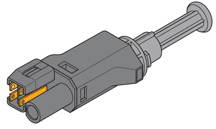
Switches F and F47 are located in a module that is installed directly next to the brake pedal. Switch F controls the brake lights. The F47 switch sends a "brake on" signal to the electronic control unit. This, for example, eliminates any risk of simultaneously applying the brakes and "Full Throttle". Switch F is designed as an N.O. contact and switch F47 as NC contact.
Signal analysis
Both switches send a "brake on" signal to the electronic control unit. Analysis of both signals ensures double safety of the entire system. The signal is analyzed to cut off fuel during coasting, improving engine smoothness and controlling the plausibility of signals from the accelerator pedal and idle switch.
Substitution function
If one or both switches fail, an emergency program is activated that adjusts the fuel injection control accordingly.
Self-diagnosis
The electronic control unit stores malfunctions in one or both switches. The signals provided by the switches can be checked in function "08", Unit for reading measured values, display group "006".
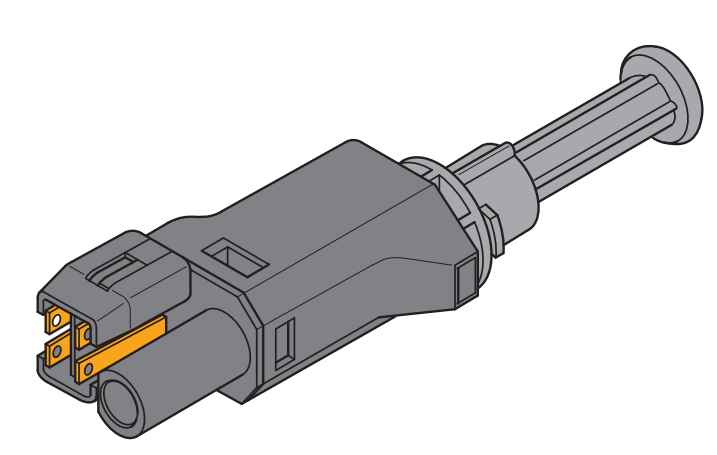
Clutch pedal switch F36
The F36 clutch pedal switch is mounted directly on the clutch pedal. This switch reports the current position of the clutch pedal to the electronic control unit. The switch is designed as an NC contact.
Signal analysis
The clutch pedal switch signal is used to influence the injector control. The amount of fuel injected is briefly reduced to improve smoothness during gear changes.
Substitution function
If there is an error in the signal, this reduction in the amount of fuel injected is not performed.
Self-diagnosis
The F36 clutch pedal switch malfunction is not stored by the electronic control unit.
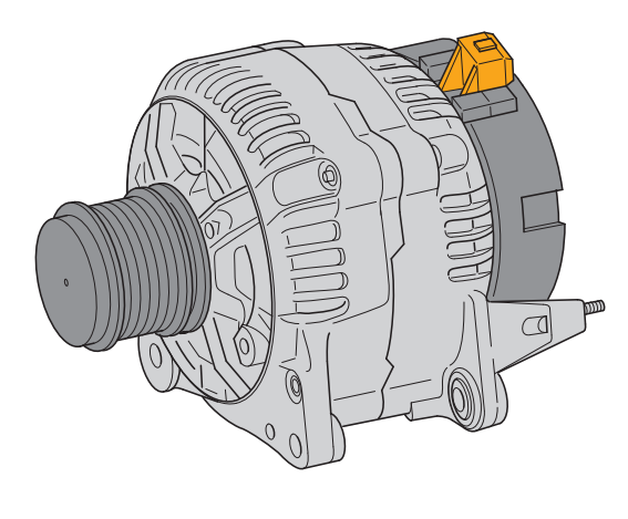
Terminal DF of the generator
The DF terminal signal is analyzed only in combination with an auxiliary heater. The available charging capacity signal exists at the DF terminal on the generator side.
Substitution function
In the event of a malfunction, the auxiliary heater switches off to avoid battery discharge.
Self-diagnosis
A lack of plausibility or a circuit break are registered as possible faults.
Air conditioner (contact 48)
The signal from pin 48 controls the operation of the AC compressor. At the same time, it is used to increase idle speed to avoid any drop in idle speed when the compressor is switched on.
Self-diagnosis
The signal is not registered in the fault memory of the electronic control unit. This signal can be checked in function "08", reading unit of measured values, display group "002".
Road speed (pin 43)
The signal on pin 43 is necessary to control the smoothness of the car. The electronic control unit controls the amount of fuel injected according to the vehicle speed. This ensures a high level of driving comfort, especially with frequent load changes. This description only applies to models equipped with cruise control; currently not intended for OCTAVIA.
Self-diagnosis
The electronic control unit registers malfunctions in this signal. This signal can be checked in function "08", reading unit of measured values, display group "006".
Cable W (pin 45)
Cable W connects the electronic control unit to the combined processor in the instrument panel J218, which incorporates the electronic immobilizer. The immobilizer signal passes through this wire to prevent unauthorized persons from starting the car. If the control unit is replaced, a new code must be entered into the combined processor.
Self-diagnosis
The electronic control unit registers a circuit break in this wire, and in this case it is no longer possible to start the engine.
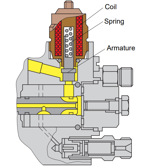
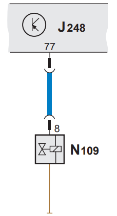
Fuel shut-off valve N109
A self-ignition engine can only be turned off by stopping the fuel supply. This is done by the fuel shut-off valve N109. It is installed in the upper half of the injection pump. In the event of a power failure, it interrupts the fuel supply to the fuel pump of the distributor. The fuel shut-off valve is electromagnetic. The fitting is used simultaneously as a shut-off fitting. If the coil is excited, the armature is attracted, the spring force is overcome and the fuel is allowed to flow.
Implementation
The fuel shut-off valve is actuated by a contact of the electronic control unit. When the contact is opened, the power supply stops and the engine stops immediately.
Substitution function
In the event of a malfunction, the vehicle no longer operates because the fuel supply is immediately cut off.
Self-diagnosis
The electronic control unit registers a malfunction. The correct condition of the shut-off fuel valve can be checked using the "03" function - the final control diagnostics.
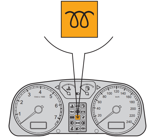
Glow period and signal lamp K29
The glow period and malfunction warning lamp K29 performs two tasks:
- Indication of the glow period, during the glow period "continuous light" is indicated;
- Warnings about malfunctions that have occurred are indicated by a "flashing light".
Malfunctions are indicated only when there is a risk of the impossibility of continuing the journey.
Implementation
The control lamp is activated by the control unit if the pre-glow system is working or if there are malfunctions in the following components:
– Needle lift sensor G80
– Engine speed sensor G28
– Modulated piston movement sensor G149
– Accelerator pedal position sensor G79
– Brake pedal switch F/F47
– Quantity regulator N146
– Start of injection valve N108
Self-diagnosis
Faults of this signal are not stored. The check is carried out by function "03" - Final control diagnostics.
Heating elements of the cooling system Q7
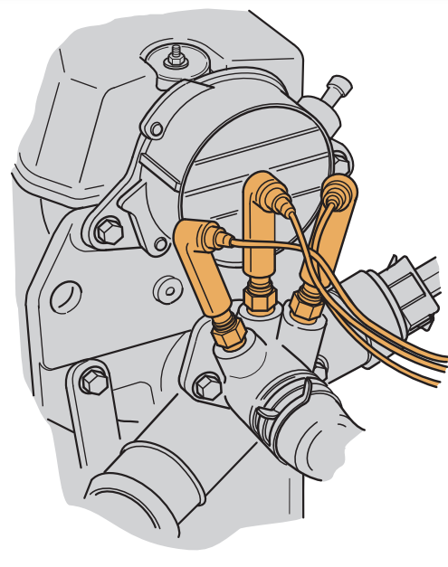
The additional heater consists of three heating elements and is screwed to the cooling nozzles of the cylinder head on the clutch side.
Implementation
If the intake manifold temperature is below approximately 5°C when the engine is started, the electronic control unit activates the Q7 heating elements in the coolant circuit via relays J359 and J360.
The initial temperature is maintained. To avoid any battery discharge, one, two or even all three heating elements are energized, depending on the available charge capacity of the alternator. For this, the generator has a special connection (terminal DF) with the control unit. The additional heater turns off when the coolant reaches a certain temperature. The shutdown temperature depends on the initial temperature. The lower the starting temperature, the higher the shutdown temperature.
Self-diagnosis
Malfunctions of the additional heater are not saved. Heating elements and relays are checked by function "03" - Final control diagnostics.
Glow plugs of the Q6 engine
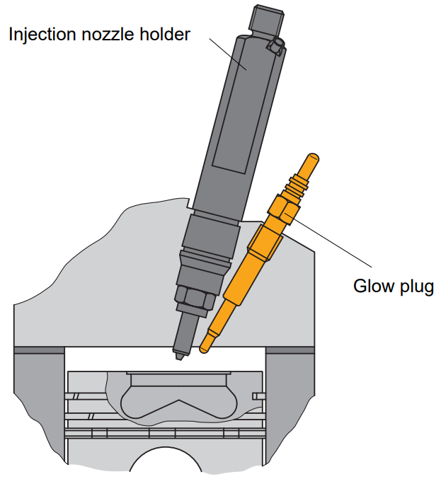
Due to the geometry of the combustion chamber, the TDI engine requires significantly longer glow plugs. Glow plugs are located so that only their tips protrude into the combustion chamber. Quick-lock allows you to quickly check and replace glow plugs.
Implementation
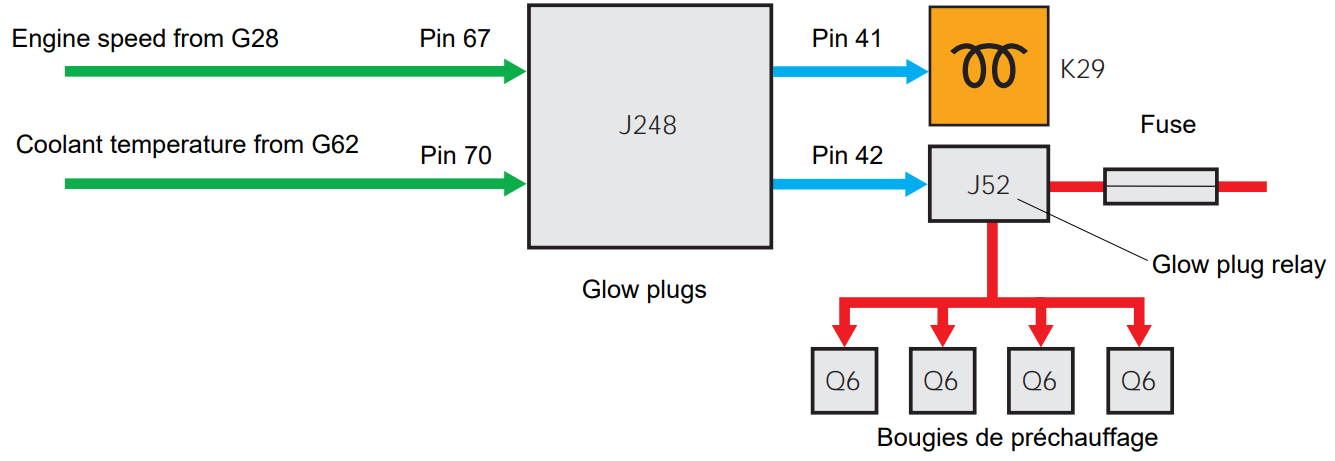
The glow plug relay is controlled by an electronic control unit. It defines the pre-glow period, the glow period and the afterglow period.
Self-diagnosis
Malfunctions in the glow plug system are not saved. Checking the glow plugs and the preheating system is carried out by the function "03" - final control diagnostics.
Quantity regulator N146
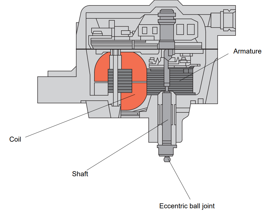
The amount regulator is installed in the upper half of the injection pump. It converts the signals received from the electronic control unit into a change in the position of the modulating piston. This is done by converting input electrical signals into specific movements of the drive shaft with an eccentric ball joint based on the electromotive principle. The drive shaft is capable of making turns at an angle of up to 60°. The spring creates a constant restoring force of the drive shaft in the direction of its initial position. The eccentric ball joint moves the modulating piston back and forth axially on the distributor piston. This makes it possible to open the control section completely (cut-off) or close it completely (full throttle).
Implementation
The accelerator pedal position signal and the engine speed signal are used in the electronic control unit as parameters to control the amount of fuel injected. Additionally, the following correction values are included:
Coolant temperature,
fuel temperature,
air mass,
Clutch pedal switch position and
Brake pedal switch position.
The electronic control calculates the regulated variable from this data, which is transmitted to the quantity regulator as a voltage.
Substitution function
If there is a fault with the quantity regulator, the engine stops. Under the action of the restoring force of the spring, the drive shaft moves to the "0" position when the voltage disappears. At the same time, the control section of the distributor piston opens completely, and the engine stops.
Self-diagnosis
Any malfunctions that occur are registered by the electronic control unit. The correct operation of the quantity regulator can be checked in function "08", Unit for reading measured values, display group "001". The current value of the entered quantity is indicated in the display field 2.
Start of injection valve N108
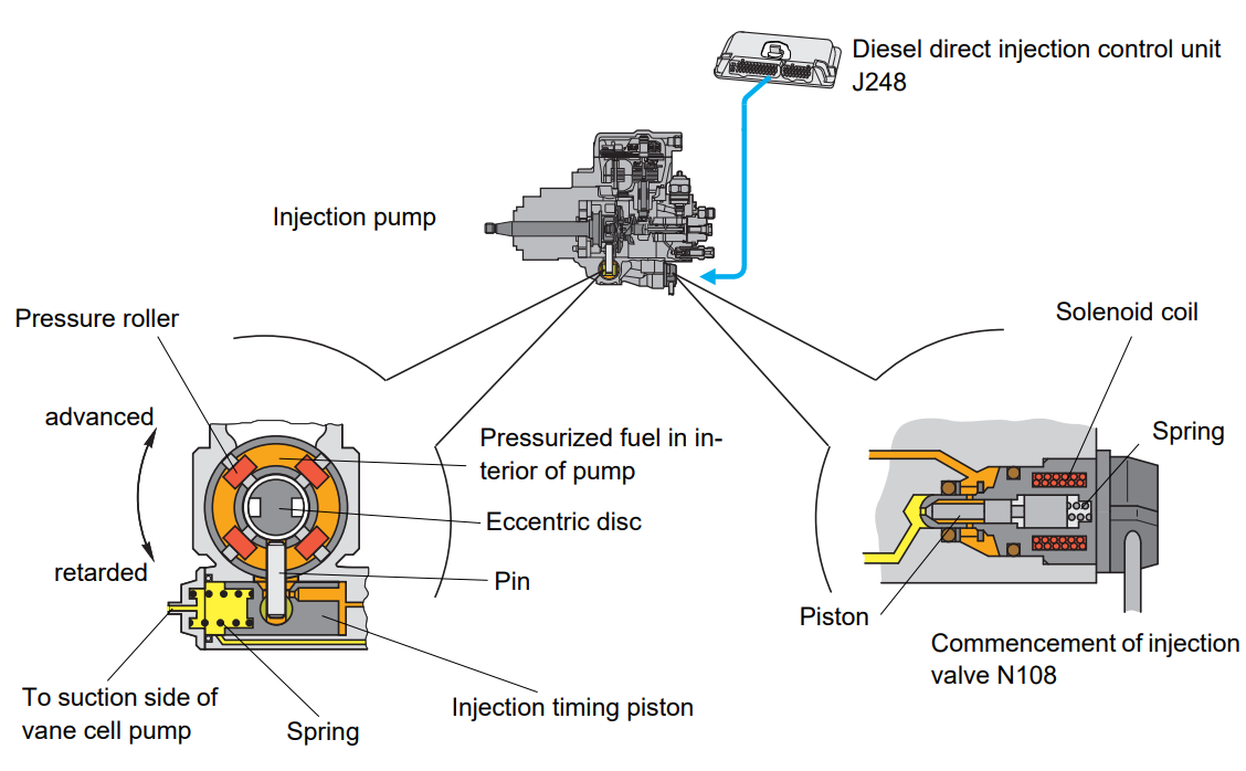
The beginning of the injector valve N108 is installed in the lower half of the injection pump. It converts the on/off ratio into a change in control pressure. This change affects the unstressed portion of the injection timing piston.
The valve is electromagnetic and consists of a piston, a spring and a coil. As a result of the action of the spring, the piston blocks the return flow of fuel in the off position. The backflow port is opened by an electronic control unit that activates the valve's solenoid coil. As a result of the action on the piston of fuel pressure, which counteracts the force of the spring, a balance of forces is established for each fuel pressure. This balance of forces provides the injection moment
the piston takes a certain position and thus changes the moment of the start of injection. The pin shifts as a result of the change in the position of the piston during the injection phase. The shift is transmitted to a radially mounted eccentric disc in the injection pump.
As a result of the connection between the trunnion and the eccentric disc, the course of the trunnion turns into a turning angle. As a result, the eccentric disk rotates in the "forward" or "retarded" direction, and the start of the injection changes accordingly.
Implementation
The needle lift sensor signal is used as an actual value parameter to calculate the signal value for the solenoid valve. The electronic control transmits a sequence of pulses of constant frequency and different phase angle to the solenoid valve.
Substitution function
In the event of a malfunction, the injection start control is deactivated. If the override function is activated, boost pressure is limited and the amount of fuel injected is reduced to avoid damage to mechanical components.
Self-diagnosis
Injection control start faults are not stored in the fault memory. The component can be checked in function "03" - Final control diagnostics. Comparison of the calculated value with the value on the map is possible in function "08", block of reading of measured values, display group "004".
Solenoid valve for regulating boost pressure N75
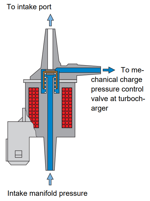
This valve limits the charge pressure depending on the value supplied by the electronic control unit. The pressure unit of the mechanical charge pressure control valve is actuated. In the off position, charge air can freely pass through the valve under pressure in the intake manifold. In the activated state, part of the supercharged air is directed to the intake port.
Implementation
The electronic control unit transmits signals to the solenoid valve that correspond to the charge pressure map. Higher or lower intake manifold pressure exists on the turbocharger boost pressure control valve by opening and closing the valve accordingly.
Substitution function
In the event of a malfunction, the pressure is limited to 0.75 bar by means of a mechanical control.
Self-diagnosis
Malfunction of the charge pressure control solenoid valve N75 is not saved by the electronic control unit. However, the charge pressure adjustment error persists. Correct operation can be checked in function "03" - Final control diagnostics. The set pressure can be read in function "08", measured value reading block, display group "011", display field 2 and the actual pressure in display field 3. The correct operation of the system can be checked by comparing both values.
Exhaust gas recirculation valve N18
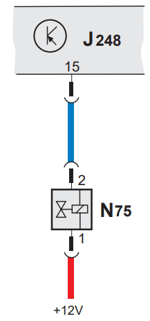
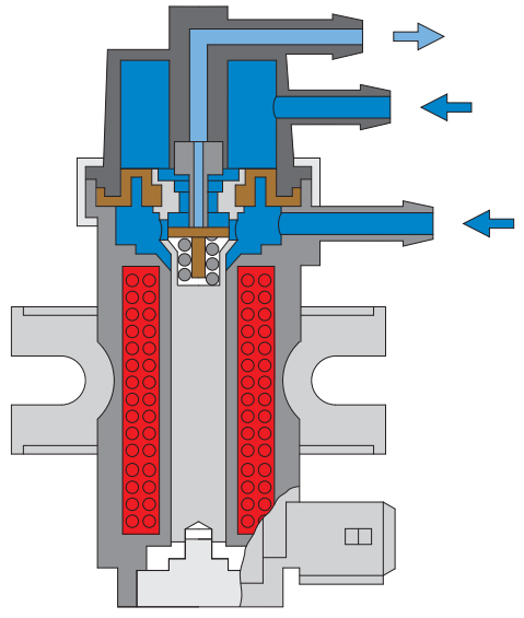
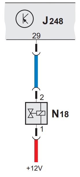
The exhaust gas recirculation valve converts the signals provided by the electronic control unit into a control vacuum for the mechanical EGR valve. In the off position, the valve closes the vacuum connection with the EGR valve. If voltage is applied, the valve opens the vacuum port. The exhaust gas recirculation valve allows very precise control of the EGR valve.
Implementation
A constant frequency voltage is applied to the valve coil. Impulses supplied by the electronic control unit are converted into mechanical movement of the armature.
Substitution function
In the event of a malfunction, exhaust gas recirculation stops, which does not affect the car's handling.
Self-diagnosis
The malfunction of the exhaust gas recirculation valve is not remembered by the electronic control unit. The correct operation can be checked in the function "03 - Diagnostics of the final control". The degree of opening of the EGR valve in percentage is indicated in function "08", reading unit of measured values, display group "003", display field 4.
Fuel consumption (pin 18)
The electronic control unit sends a signal about the engine speed to the combined processor in the instrument cluster J218. This signal is needed, for example, to indicate engine speed, dynamic oil pressure, etc. In the event of a malfunction, these readings no longer work. The fault is not saved.
Fuel metering control
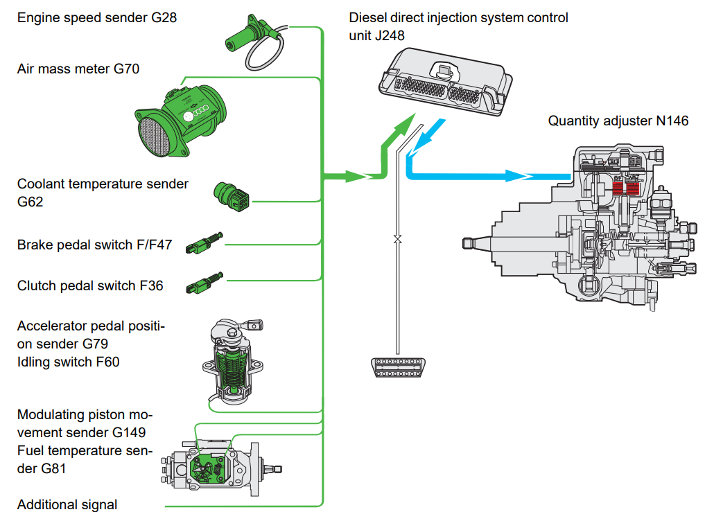
The electronic control unit controls the quantity regulator depending on the parameters of injection quantity, engine speed, engine torque, ride comfort and starting. Based on the stored value of the map, the amount of injected fuel is additionally determined by various values provided by the sensors. The control unit for the quantity regulator receives the following sensor signals:
– accelerator pedal position;
– Air mass;
– Idle switch position;
– Adjusting the position of the piston;
– Coolant temperature;
– brake pedal position;
– Fuel temperature;
– clutch pedal position;
– Engine speed;
– Traffic speed signal.
Exhaust gas recirculation
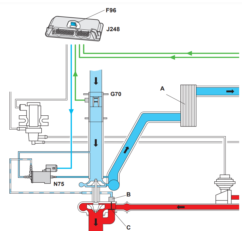
Pressure block B on charge pressure valve C is pressurized by charge pressure control solenoid valve N75. Electrical signals are applied to valve N75 by an electronic control unit. This allows you to influence the pressure of the charge according to the map. The intake manifold temperature and pressure are monitored by the G71/G72 intake manifold pressure and temperature sensor. Differences from the set value are regulated accordingly. Temperature is controlled through its effect on air density. The charge pressure map is adjusted according to the air pressure by the F96 altitude sensor so that the engine is always supplied with approximately the same mass of air. From about 1,500 meters above MSL, the boost pressure is reduced to prevent the turbocharger from over-revving.
Charge pressure control
Charge pressure is controlled by varying the on/off ratio, with the average pressure controlled in conjunction with atmospheric pressure. The on/off ratio is generated by comparing the sensor signal and the map value. The charge pressure control solenoid valve is actuated by this signal. This valve opens or closes the flow of charge air to the pressure unit. If high air pressure is supplied to the pressure unit, it opens the valve in the turbocharger housing. Exhaust gases pass through this valve directly to the exhaust, without passing through the turbocharger. Charge pressure is regulated depending on altitude and air temperature. As the air pressure drops, the boost pressure is reduced to prevent damage to the turbocharger.
Auxiliary heater system
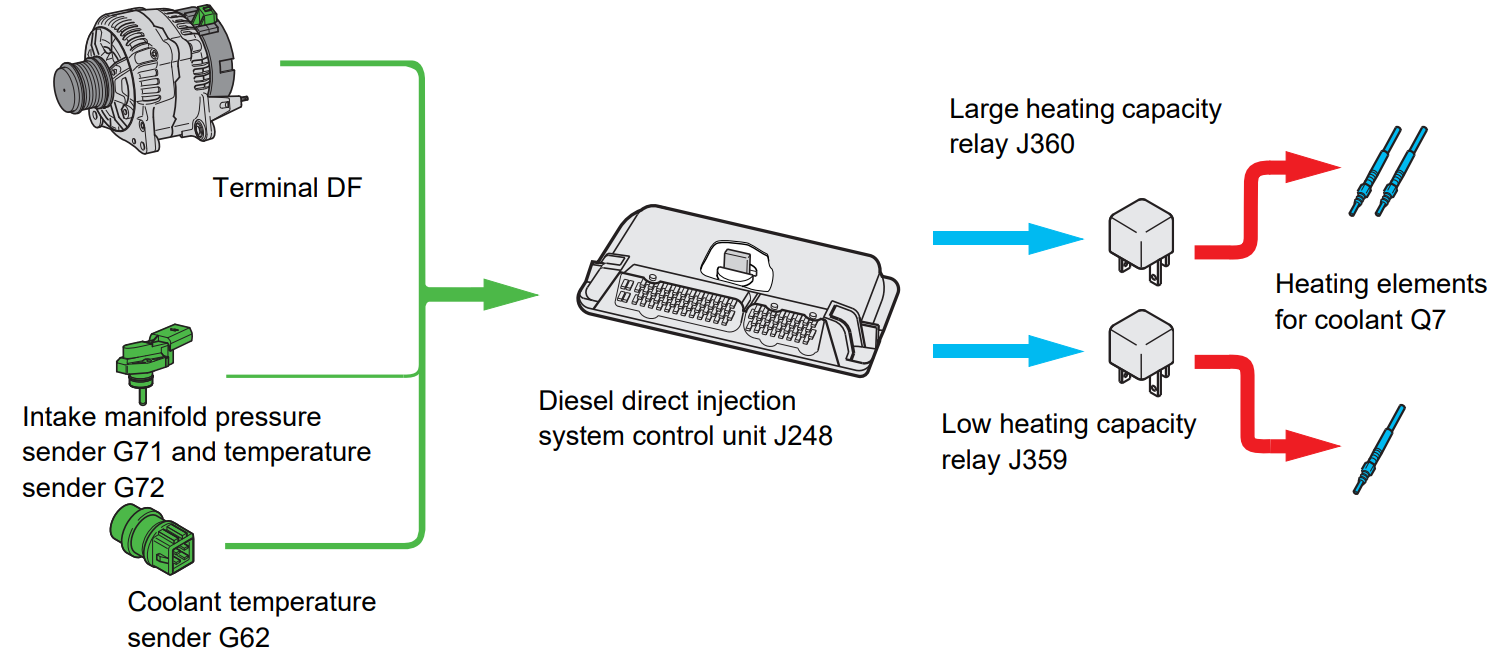
As a result of the high efficiency of the TDI engine, only a very small amount of heat is dissipated into the coolant. The coolant is heated electrically by an auxiliary heater if the outside temperature is low. A higher capacity alternator is installed to provide sufficient power at all times.
Activation
The auxiliary heater operates according to the temperature of the coolant and the outside temperature. The additional heater is switched on if the coolant temperature is below 5°C. It remains in operation for a certain time depending on the initial temperature.
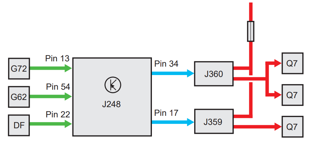
The heating power is connected according to the available power of the generator. The output power is measured for this purpose at the DF terminal. The auxiliary heater is turned on through relays J359 and J360. If necessary, you can connect one, two or three heating elements.
Glow plug system
During the compression phase, high pressure and high temperature are created in the combustion chamber. This greatly affects the combustion process. Heat dissipation is low due to the small surface area of the combustion chamber. Preheating is necessary only at low temperatures. The main difference between the three phases of glow:
– Pre-lighting period;
– Glowing period;
– Afterglow period.
System control
The glow plug system is controlled by an electronic control unit. Preheating is activated only when the coolant temperature is below +10°C. The preheating period is longer, the colder the coolant.
The pre-glow is followed by a 5-second glow period. The afterlight is activated when the coolant temperature is below +20°C when the engine is started for about 30 seconds. A total glow period of 90 seconds is possible depending on the coolant temperature. The auxiliary light turns off when the engine speed exceeds 2500 rpm.
Emission characteristics
Pollutants in the exhaust
The most common pollutants found in the exhaust gases of diesel engines are already familiar to you from the information provided for the 1.9 liter engine. atmospheric diesel engine. The specific characteristics of the TDI engine with regard to harmful substances, in particular nitrogen oxides (NOx), are explained in the section on exhaust gas recirculation. 1.9-l. The TDI engine has a wide range of measures aimed at reducing pollutant levels and improves the emission limits that have been in place since 1996, while achieving excellent fuel economy. The measures taken to reduce pollutants in exhaust gases and how they interact with each other are explained in detail below.
Reduction of pollutants
Measures suitable for reducing the formation of particulates and hydrocarbons (HC) have the effect of increasing the proportion of nitrogen oxides. If oxide emissions are to be reduced, then higher levels of other exhaust elements must be accepted, and at the same time fuel consumption will also be greater. The lowest possible exhaust gas emissions were one of the main criteria even at the design stage of all components involved in combustion, such as the injection nozzle, the piston bowl, the geometry of the combustion chamber. Improvements in the engine management system also contributed to the optimization of the combustion process. The main influencing factors are the start of injection, exhaust gas recirculation, and the oxidation catalytic converter.
The effect of the start of the injection
If the start of the injection is slowed down, the level of nitrogen oxides in the exhaust can be reduced. This results in reduced engine power and increased levels of hydrocarbons (HC) and particulate matter. These exhaust elements can be improved by installing a catalytic converter. The result of these measures is an increase in fuel consumption by approximately 4%. Effect of Exhaust Gas Recirculation (EGR) Exhaust gas recirculation in the combustion chamber can reduce the oxygen content. The result of this measure is a reduction in nitrogen oxide emissions, although it may lead to an increase in particulate matter emissions under certain operating conditions.
Catalytic oxidation neutralizer
The main part of emissions of gaseous pollutants (HC, CO) and solid particles is converted into carbon dioxide (CO2) and water vapor in the catalytic converter. Nitrogen oxides (NOx) cannot be converted by the catalyst.
Functional diagram
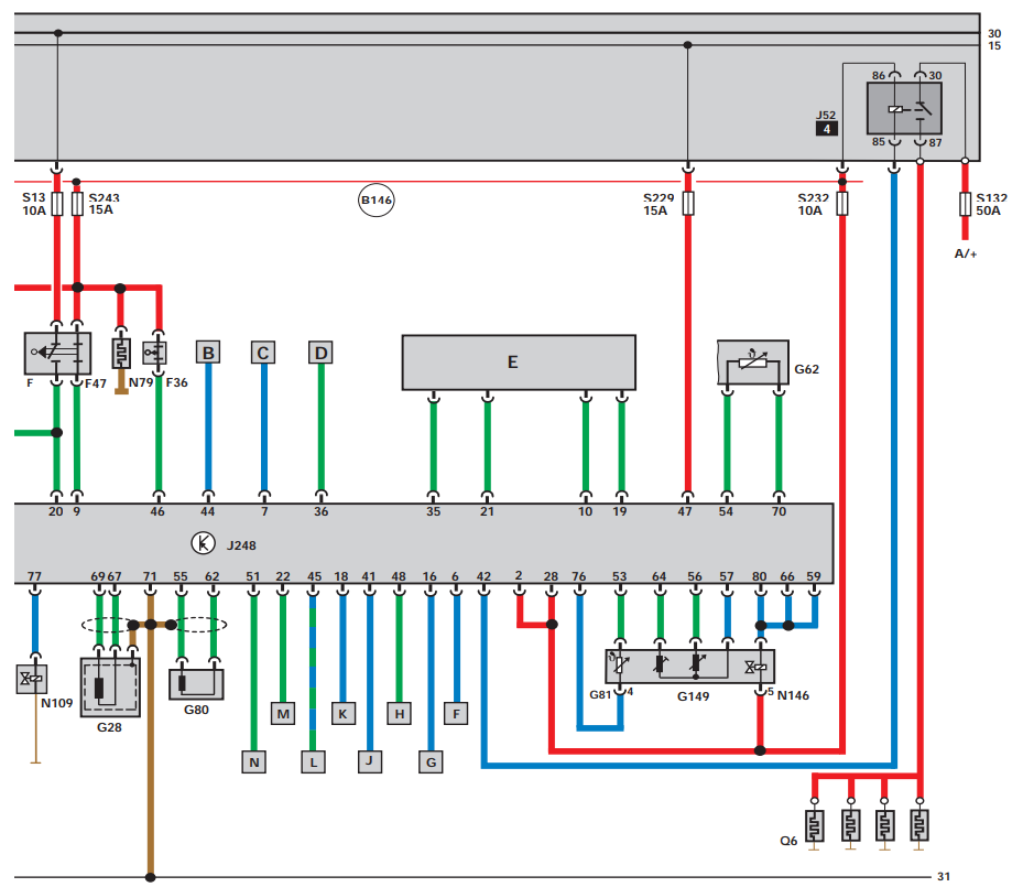
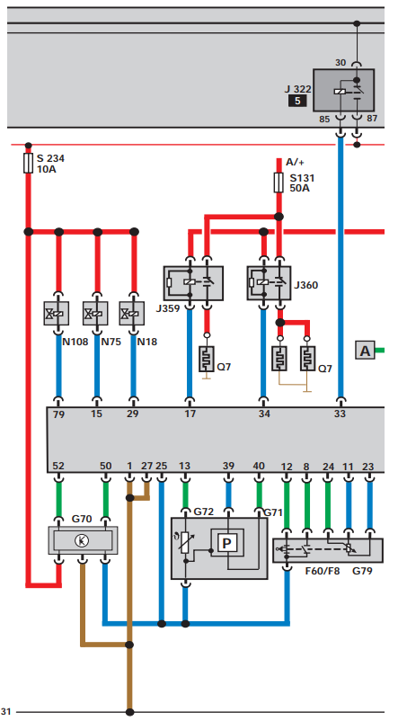
The block diagram is a simplified flow diagram and shows how all the components of the direct injection diesel control system are interconnected.
Components
A/+ battery is positive
F Brake light switch
F8 Kickdown switch
F36 Clutch pedal switch
F47 Brake pedal switch
F60 Idle switch
G28 Engine speed sensor
G62 Coolant temperature sensor
G70 Air mass meter
G71 Pressure sensor in the intake manifold
G72 Intake manifold temperature sensor
G79 Accelerator pedal position sensor
G80 Needle lift sensor
G81 Fuel temperature sensor
G149 Modulated piston movement sensor
J52 Glow plug relay (engine)
J248 Diesel direct injection system control unit
J322 Diesel direct injection system relay
J359 Relay of low thermal capacity
J360 Relay of high thermal capacity
N18 Exhaust gas recirculation valve
N75 Charge pressure control solenoid valve
N79 Crankcase breather heating element
N108 Injector valve start
N109 Fuel shut-off valve
N146 Quantity regulator
Q6 Glow plug - engine
Q7 Heating elements of the cooling system
S... Fuses
Additional signals
A Stop lights
B Kickdown signal
C Accelerator pedal position
D Engine control signal (only with automatic transmission)
E Designed for cruise control system (CCS)
F Engine speed signal
G Shutdown of the AC compressor
H AC compressor in standby mode (increasing idle speed)
J Glow plug control lamp
K Fuel consumption signal
L Wiring for diagnostics and immobilizer
M Terminal DF
N Combined processor in the instrument panel