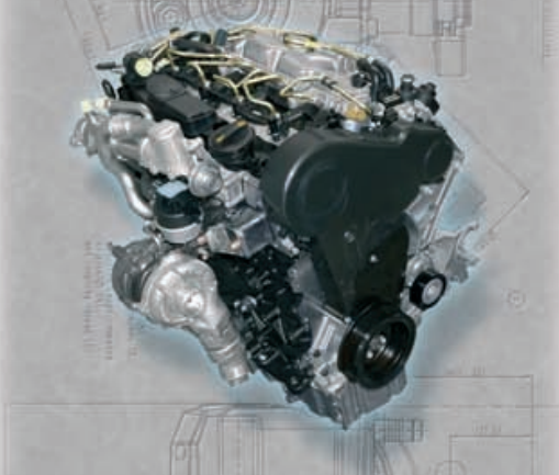
Audi 2.0 l TDI engine with Common Rail injection system

AvtoAd
11/08/2022
The 105 kW (143 hp) 2.0 L TDI engine with Common Rail (CR) injection marks the beginning of the transition to a new generation of powerful and economical diesel engines. It demonstrates the new capabilities of the TDI scheme and makes it suitable for tomorrow's requirements, which are defined above all by the need to minimize the impact on the environment.
The 2.0 L TDI-CR engine is based on the successful 2.0 L TDI with pump-injectors, but at the same time, the combination of the two-liter TDI unit with the Common Rail injection system allows you to take it to a new level. The new 2.0-liter TDI-CR engine is produced by the Audi Hungaria Motor plant in Deri (Gyr), Hungary, and already today meets the strict requirements of the Euro 5 standard, which came into force only in 2010.
The use of Common Rail injection technology gives the .l TDI-CR engine very significant advantages in terms of exhaust toxicity, noise, weight and dimensions (constructive height).
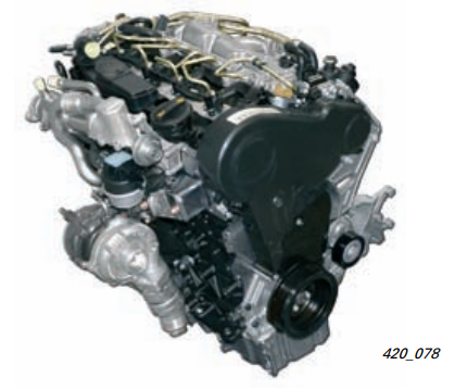
The most important innovation is the switch to a common rail battery injection system. When equipped with a particulate filter, the new engine meets the requirements of the current Euro 4 standard. In some markets, the engine is also offered without a particulate filter, in this case meeting the requirements of the Euro 3 standard.
Content
3. Engine letter designation scheme.
4. Cylinder block.
5. Crank and connecting rod mechanism.
6. Crankshaft.
7. Pistons.
9. Head of the cylinder block.
10. Camshaft drive of intake valves.
12. Toothed belt of the timing drive.
13. Attachment drive.
14. Dampers of intake channels.
15. The principle of operation of intake valves.
16. Lubrication system.
17. Crankcase ventilation system.
18. Rough oil separation.
19. General diagram of the path of crankcase gases.
20. Thin oil separation. Small pressure difference.
21. Fine oil separation. Large pressure difference.
23. Cooling system.
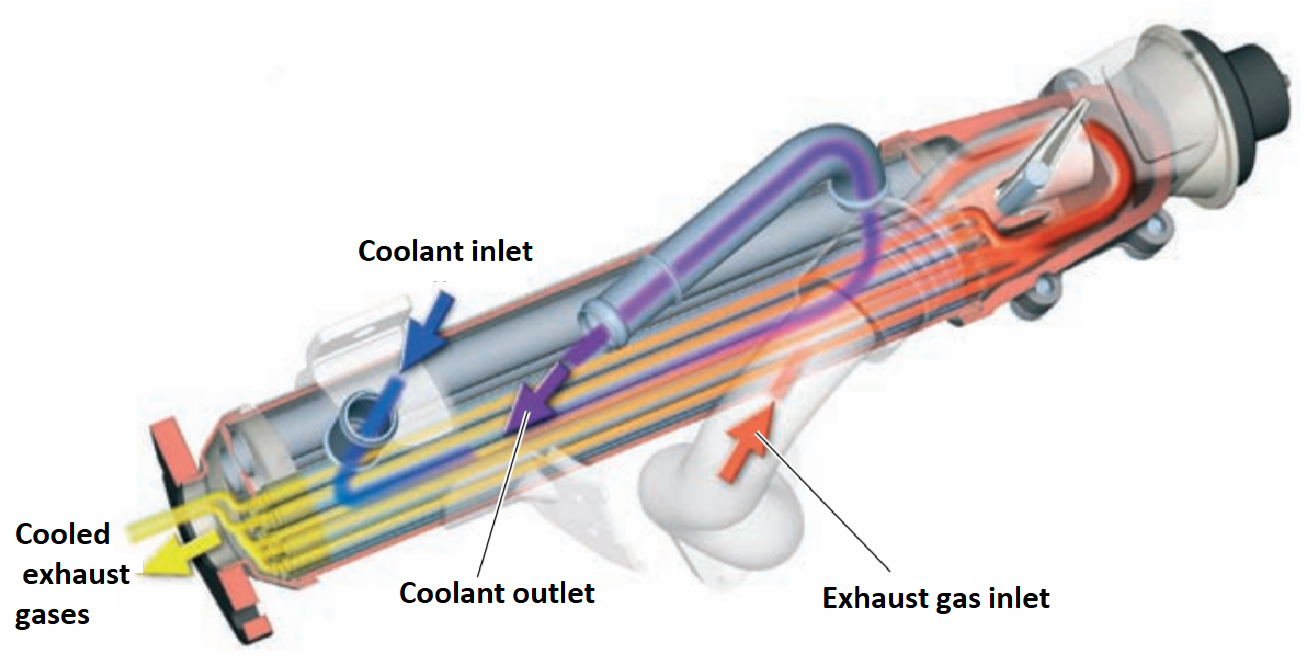
24. Low-temperature cooling of exhaust gases during recirculation.
25. Radiator of the exhaust gas recirculation system.
26. Common Rail injection system.
27. Fuel system (general diagram).
28. Additional fuel pump.
29. Additional fuel pump V393 and fuel filter.
31. Control thermocouple.
32. Technical features of the injection system.
33. Nozzles.
34. Fuel injection pump CP 4.1.
35. Device diagram.
36. High pressure zone.
37. Admission.
38. Work flow.
40. Low pressure area.
41. Fuel rail pressure control.
42. Regulation with the help of the fuel pressure regulator N276.
43. Regulation with the help of the fuel metering valve N290.
44. Regulation with the help of both valves.
45. Fuel pressure regulator N276.
46. The regulator is in the free state (when the engine is turned off).
47. A control signal is applied to the regulator (engine on).
48. Sensors.
50. CAN bus interfaces (CAN drive).
51. Turbocharger.
52. Air flow retarder.
53. Boost pressure adjustment.
54. N75 boost pressure limiting solenoid valve.
55. Boost pressure sensor G31/ intake air temperature sensor G42.
56. Intake air temperature sensor G42.
57. Boost pressure regulator position sensor G581.
58. Exhaust gas recirculation.
59. Exhaust gas recirculation valve N18.
60. Potentiometer of the exhaust gas recirculation system G212.
61. N345 exhaust gas recirculation system radiator switch.
63. Throttle potentiometer G69.
64. Soot filter.
65. Degree of filling and types of regeneration of the soot filter of the 2.0 L TDI-CR engine.
66. Pre-heating system.
67. Control signals of glow plugs with a phase shift.
Technical features
- Common Rail injection system with injectors with piezo crystal valves.
- Soot filter with preliminary oxidation catalyst.
- Intake manifold with inlet valves.
- Electric exhaust gas recirculation valve.
- Turbocharger with adjustable turbine geometry and regulator position sensor.
Specifications
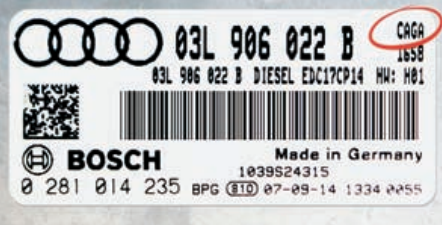
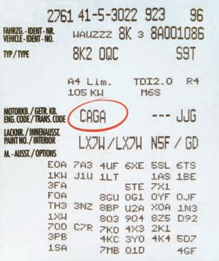
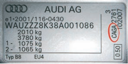
- Engine Letter: CAGA.
- Design: 4 cylinders, sequential.
- Working volume, cm3: 1968.
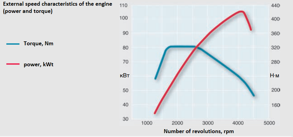
- Power, kW (hp): 105 (143) at 4200 rpm.
- Torque, Nm: 320 at 1750 to 2500 rpm.
- Number of valves per cylinder: 4.
- Cylinder diameter, mm: 81.
- Piston stroke, mm: 95.5.
- Compression ratio: 16.5:5.
- Engine management system: Bosch EDC 17.
- Neutralization of toxic substances in the exhaust gas: Oxidation catalyst, liquid-cooled exhaust gas recirculation, maintenance-free particulate filter.
- Compliance with OG toxicity standards: Euro 4.
Engine Lettering Scheme
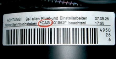
To reduce the number and systematize engine letter designations, a new, fourth character is added to the three-digit letter designations. The corresponding power and torque characteristics are set by the software of the engine control unit. Engines that meet different emission standards are not assigned a changed letter designation.
Sticker on the engine control unit:
Car data sticker:
Engine letter sticker:
Manufacturer's plate:
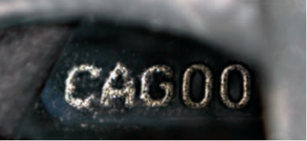
Letter designation of the engine in the cylinder block:
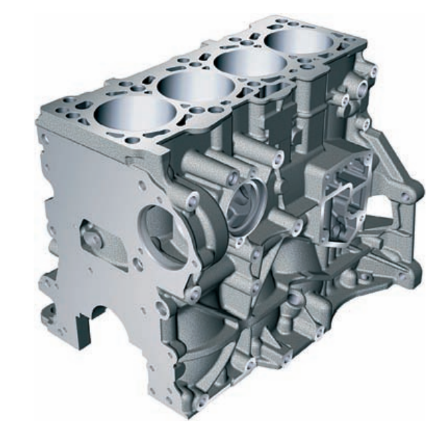
Cylinder block
The cylinder block of the 2.0 L TDI-CR engine is made of gray cast iron with plate graphite, the distance between the cylinder axes is 88 mm. According to its geometric dimensions, it is based on a 2.0 L TDI engine with pump injectors.
Crank and connecting rod mechanism
Crankshaft
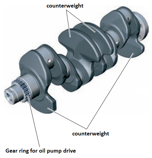
Due to high mechanical loads, a forged crankshaft is installed on the 2.0 L TDI-CR engine. To reduce the load on the supports of the crankshaft structure, only 4 counterweights are provided instead of the usual 8. This also helps to reduce engine vibrations and reduce the noise of its operation.
Pistons
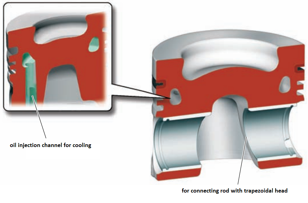
As with its predecessor, the 2.0-liter 125 kW TDI engine with pump-injectors, there are no valve recesses in the bottoms of the pistons. Thanks to this, a reduction in the volume of the combustion chamber is achieved. To cool the area of the piston rings, the piston has an annular cooling channel, which injects oil through special nozzles.
The combustion chamber in the piston, in which the air and fuel are swirled and mixed, is precisely matched to the shape of the nozzle flares and generally has a wide and flat shape. (This facilitates homogeneous mixture formation and prevents the formation of soot particles).
Balancing shaft block
The 2.0 L 105 kW TDI-CR engine is equipped with a block of balancer shafts, which is located under the crankshaft in the oil pan. The block of balance shafts works from the crankshaft with the help of a gear drive. In the block of balancer shafts, together with it, the Duocentric pump is located.
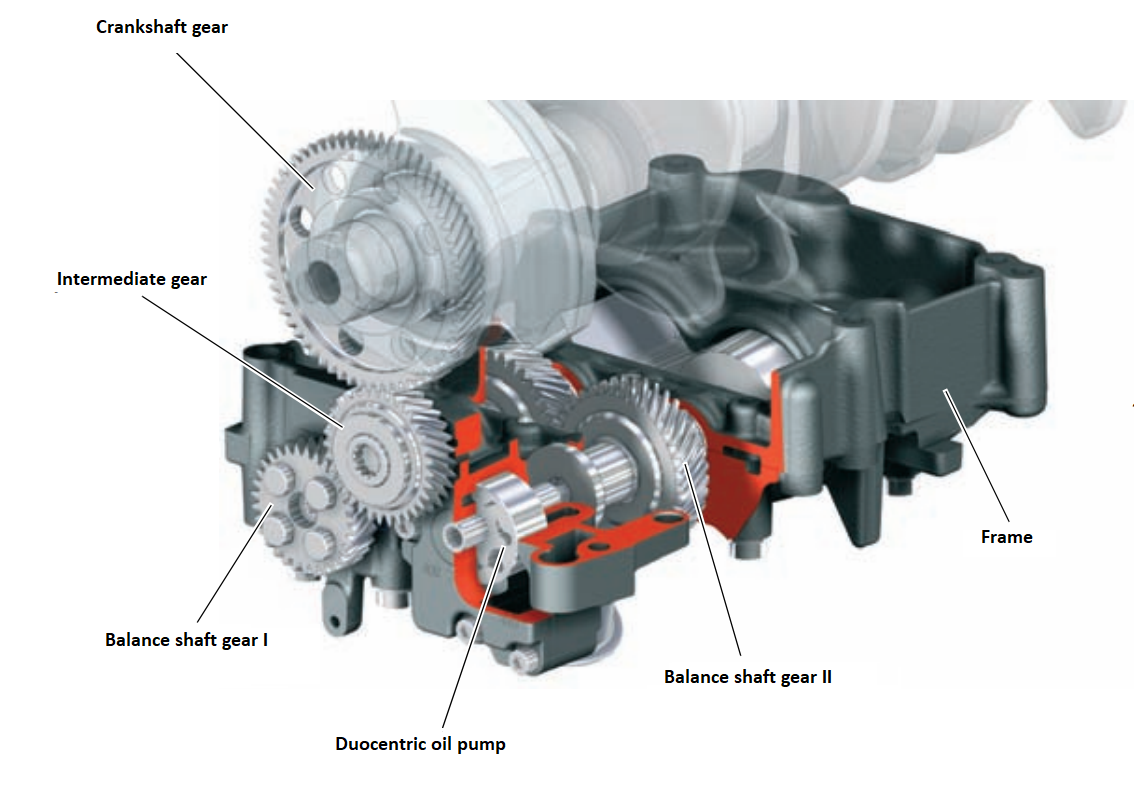
The balancer shaft assembly consists of a cast gray cast iron housing, two counter-rotating balancer shafts, a helical gear, and a Duocentric oil pump integrated into the assembly. The rotation of the crankshaft is transmitted to an intermediate gear located on the outside of the block housing. This gear, in turn, drives the balancer shaft I. The balancer shaft I, through a gear pair located inside the block housing, drives the balancer shaft II and through it the Duocentric oil pump. The gear is designed in such a way that the balancer shafts rotate at twice the speed of the crankshaft. The side hole of the gear engagement is adjusted using a special cover of the intermediate gear wheel. At the beginning of engine operation, this coating wears off.
Important: after removing or loosening the fastening of the intermediate gear or balance shaft I, the intermediate gear must be replaced with a new one.
The head of the cylinder block
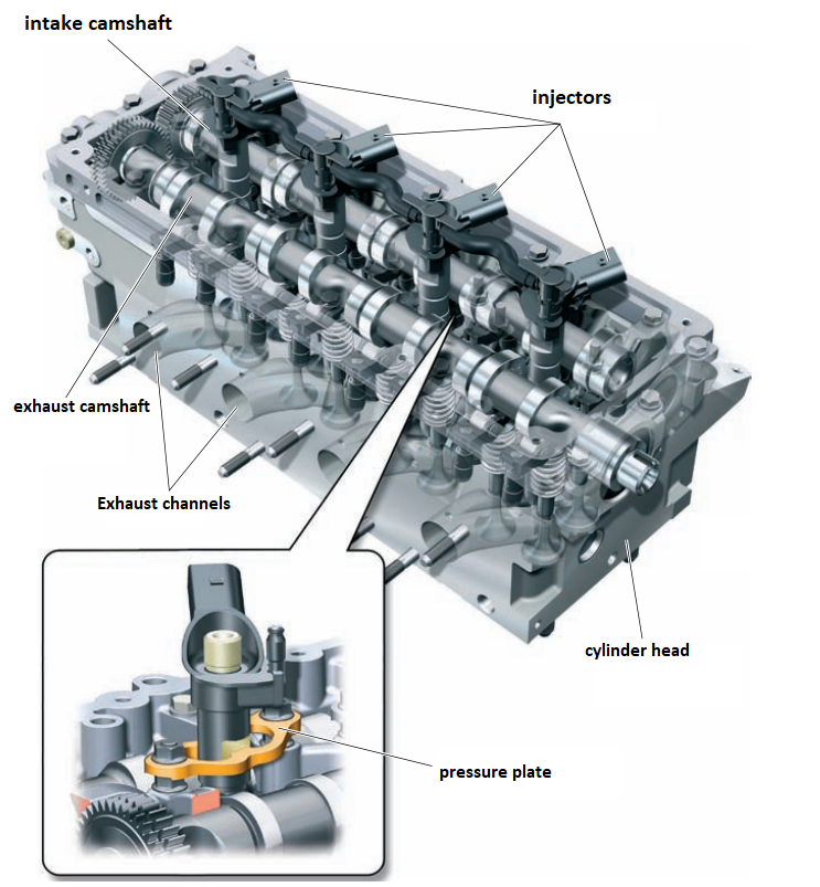
The 2.0-liter TDI-CR engine is equipped with an aluminum cylinder head with a transverse cooling channel and two intake and two exhaust valves per cylinder. The fuel injectors are located vertically. The overhead camshafts of the intake and exhaust valves are connected to each other with the help of a toothed cylindrical pair with side clearance compensation. The camshafts are driven with the help of a toothed belt from the crankshaft and through a toothed pulley on the camshaft of the exhaust valves. The valves are actuated with the help of roller rockers, which ensure minimal friction losses with hydraulic compensators. The injectors are fixed in the cylinder head with pressure plates. Access to them for removal is provided through the hatches of the valve cover.
Intake valve camshaft drive
The intake and exhaust camshafts are connected to each other with the help of a cylindrical gear pair with side clearance compensation. At the same time, the intake camshaft gear is secondary, and the exhaust gear is the main (driving) gear. Compensation of side clearances ensures silent operation of the gear pair of the camshaft drive of the intake valves.
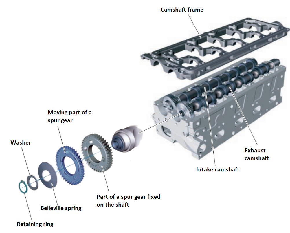
The wider (immovable) part of the cylindrical gear wheel is rigidly fixed on the camshaft of the exhaust valves. In its front part there are six protrusions. The narrower (moving) part of the cylindrical gear wheel can move in the radial and axial directions and thus compensates for the gap in the engagement. On the back of the narrow part there are recesses for six protrusions.
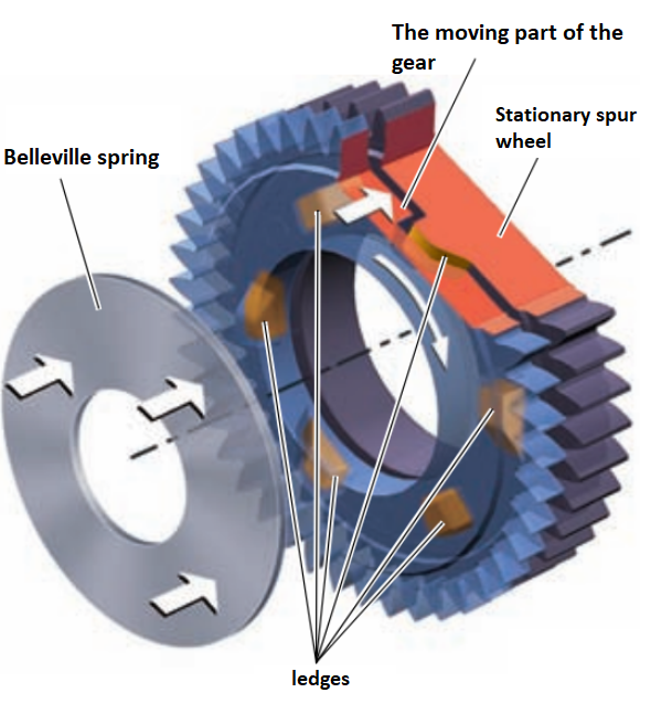
Both parts of the cylindrical gear wheel are pressed against each other (in the axial direction) by a disk spring. At the same time, due to the inclined planes of protrusions and depressions, they tend to return to each other (relative to the longitudinal axis).
4 valves per cylinder
For each cylinder, 2 intake and 2 exhaust valves are vertically installed in the block head.
The nozzle, located vertically (along the axis of the cylinder), is installed exactly in the center of the combustion chamber in the piston.
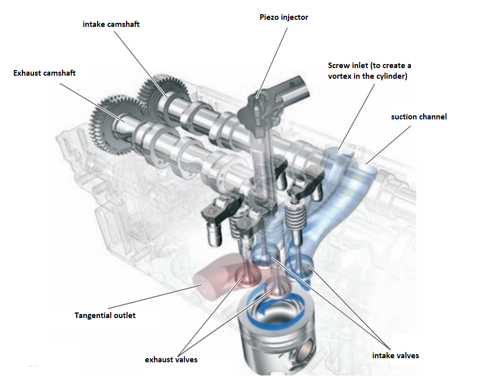
The shape, size and location of the intake and exhaust channels ensure good filling and optimal gas exchange in the combustion chamber.
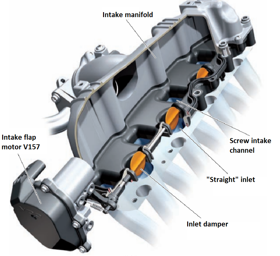
One of the intake channels is designed as a screw, the other as a straight suction channel. The use of a screw channel allows you to give the incoming air the necessary swirl.
The straight channel ensures good filling of the combustion chamber, especially at high revolutions.
Timing belt drive
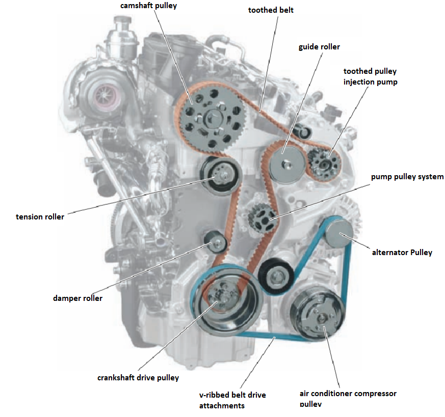
The camshaft, the cooling system pump and the Common Rail injection pump are driven through a toothed belt drive.
Attachment drive
Such attached units as the generator and air conditioning compressor are driven from the crankshaft with the help of a poly-V belt. A coating is applied to the working surface of the belt, which improves its adhesion to the pulleys. It also helps to reduce the noise that normally occurs in wet or cold weather conditions.
Dampers of intake channels
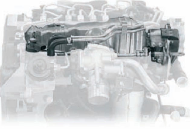
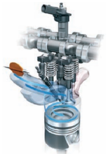
In the channels of the intake manifold, continuously adjustable flaps are installed. By changing the position of the valves of the intake channels, depending on the engine speed, the degree of swirling of the air entering the combustion chamber can be changed.
The valves of the intake channels are actuated with the help of the V157 air damper electric motor rod. This executive electric motor is controlled, in turn, by the engine control unit. The G336 intake valve position sensor (potentiometer) is built into the executive electric motor, which transmits information about the current actual position of the valves to the engine control unit.
The principle of operation of intake valves
At idle and in the range of low revolutions, the valves of the intake channels are closed. Air enters the cylinders only through screw channels, which ensures good mixture formation. When the engine is started, when working in emergency mode or at full load, the valves of the intake channels are open.
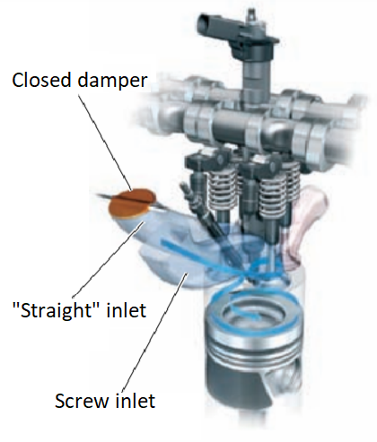
When the vehicle is in motion, the position of the flaps is continuously adjusted according to changes in engine speed and load. Thus, optimal filling of the cylinders is ensured in each mode of engine operation.
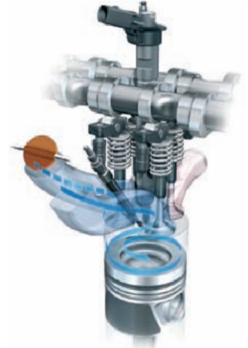
Starting from revs of approx. 3000 rpm, the inlet valves are fully opened. This ensures maximum air supply and optimal filling of the combustion chamber.
Lubrication system
Components:
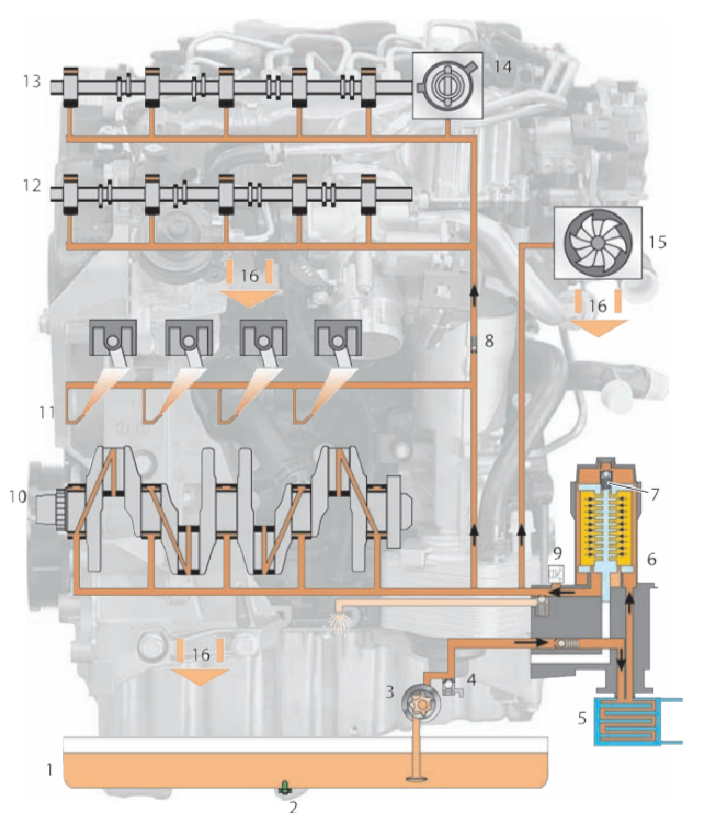
1. Oil pan.
2. Oil level and temperature sensor G266.
3. Duocentric oil pump.
4. Oil pressure control valve.
5. Oil radiator.
6. Oil filter.
7. Bypass valve.
8. Oil return valve.
9. Oil pressure sensor F1.
10. Crank shaft.
11. Nozzles for cooling the piston.
12. Camshaft of exhaust valves.
13. Camshaft of intake valves.
14. Vacuum pump.
15. Turbocharger.
16. Oil return.
17. Mesh filter.
18. Throttle.
A Duocentric oil pump (3) is used to create an oil circuit of the required pressure. It is built into the block of balancer shafts and is driven from one of the balancer shafts. The oil pressure control valve (4) acts as a safety valve. It prevents damage to engine parts due to too high oil pressure, for example, when operating at high speeds at low air temperatures. The bypass valve (7) opens when the oil filter is clogged/obstructed, thereby ensuring lubrication of engine parts and assemblies.
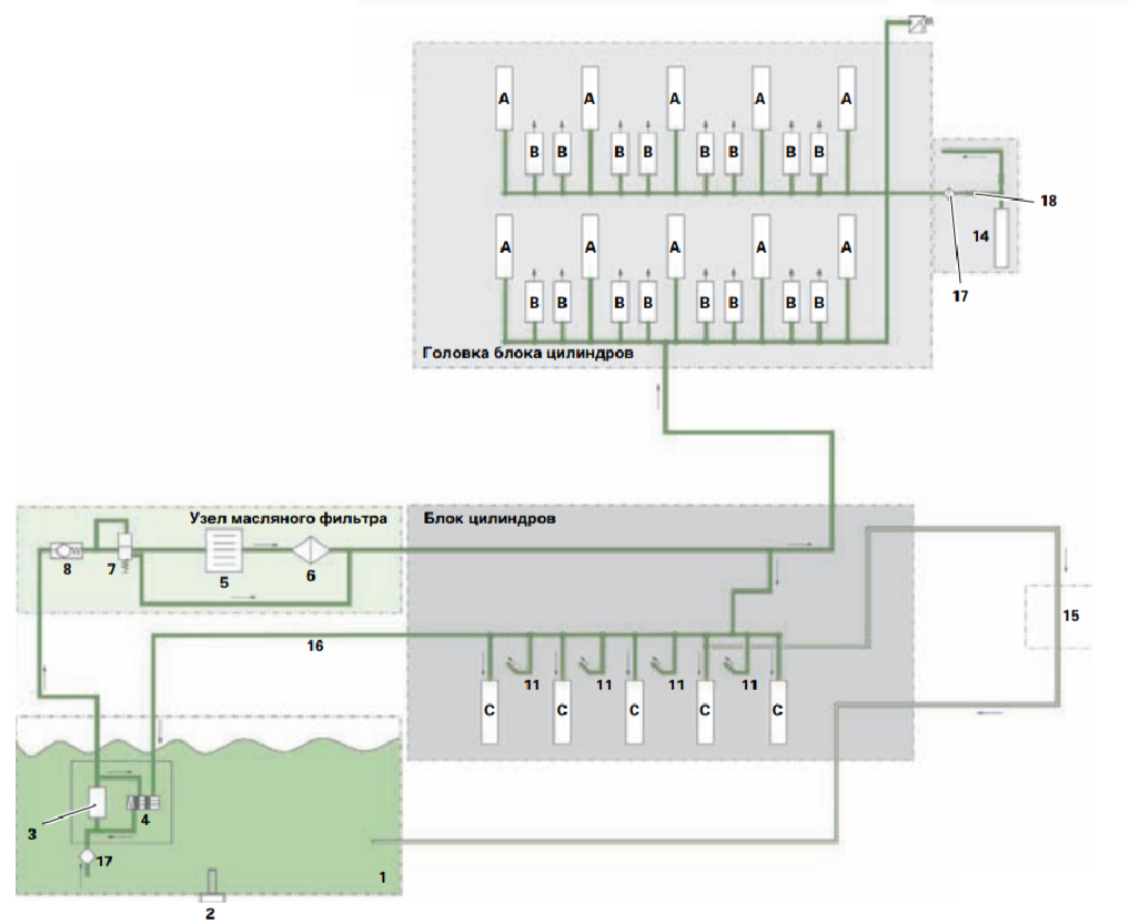
A. Camshaft bearings.
B. Hydraulic valve compensator.
C. Main Bearings.
Crankcase ventilation system
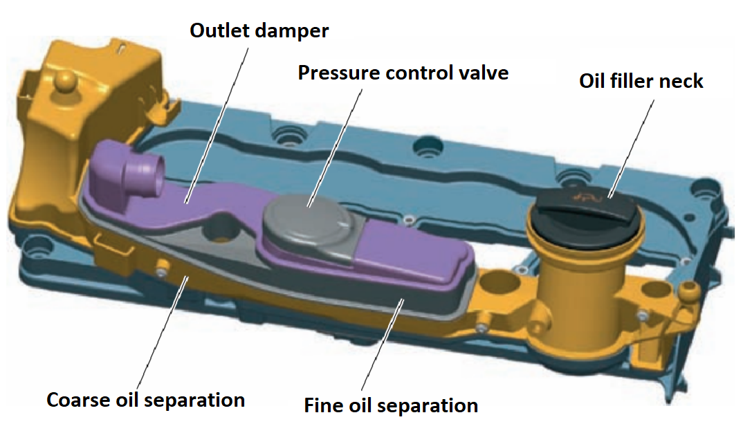
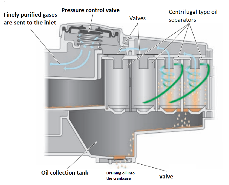
During the operation of an internal combustion engine, crankcase gases break through the piston rings into its crankcase. To remove these gases mixed with oil mist, the crankcase ventilation system serves, after which they are fed back into the intake tract to avoid environmental pollution. Requirements for the environmental friendliness of engines, which have grown in recent years, make it necessary to use effective methods of oil separation. The use of several stages of oil separation allows you to minimize the supply of oil residues to the combustion chambers of the engine, and thereby the formation of soot.
Oil separation is carried out according to the following principle:
- coarse separation of oil,
- thin separation of oil,
- compartment in the output tranquilizer.
The components of the crankcase ventilation system are integrated (together with the oil filler neck and the receiver of the vacuum system) into the valve cover of the cylinder head.
Rough separation of oil
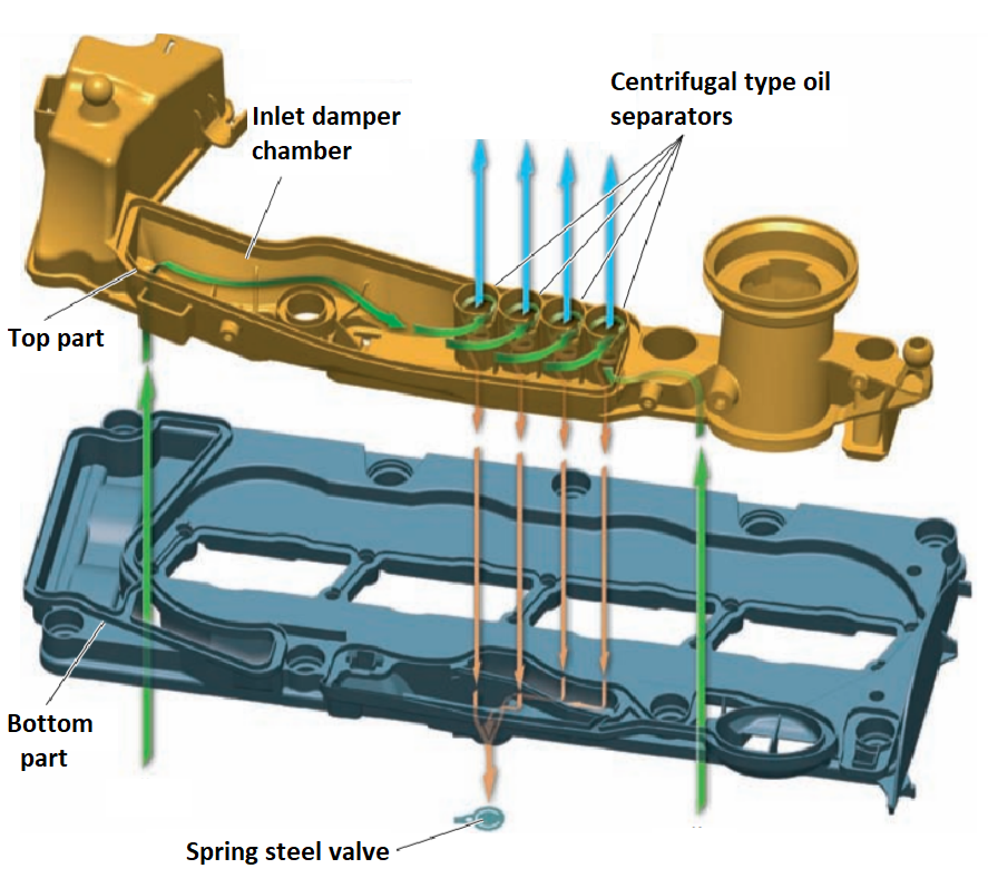
From the working areas of the crankshaft and camshafts, crankcase gases enter the intake silencer. The chamber of the inlet stabilizer is made as one unit with the valve cover. In the inlet silencer, the movement of crankcase gases slows down, and large drops of oil settle on the walls and accumulate at the bottom of the chamber. Oil flows into the cylinder head through holes in the bottom of the chamber of the inlet stabilizer.
General diagram of the path of crankcase gases

Thin oil separation. Small pressure difference
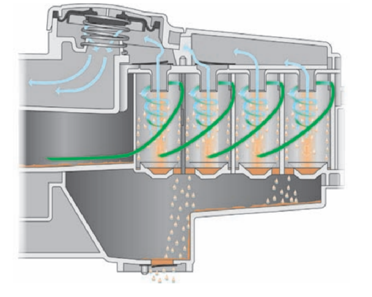
Fine oil separation is carried out with the help of four centrifugal type oil separators. Depending on the pressure difference between the crankcase and intake manifold, the spring steel valves activate two or four centrifugal oil separators. Due to the shape of the centrifugal oil separator, the air passing through it comes into a rotating motion.
Fine separation of oil. Large pressure difference
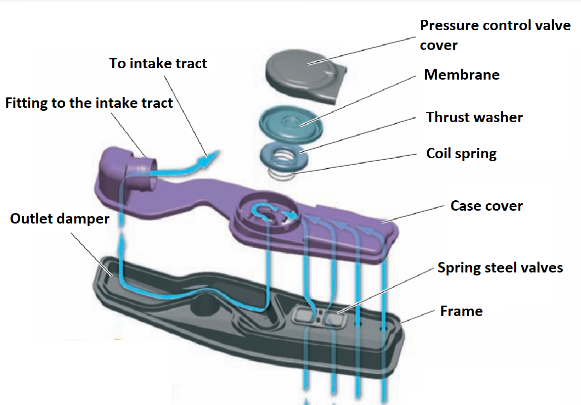
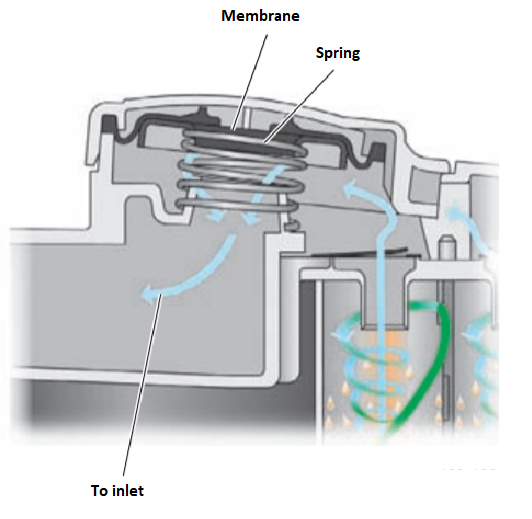
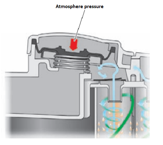
The pressure control valve controls the pressure in the crankcase ventilation system. It consists of a membrane and a spring. The pressure control valve allows crankcase gases to be diverted to the intake channel without creating excessive vacuum in the crankcase. Too low pressure (high vacuum) in the crankcase can damage the engine seals.
Pressure control valve
With a slight vacuum in the intake channel, the spring opens the valve.
When there is a significant vacuum in the intake channel, the valve closes.
The pressure control valve is open
Output tranquilizer
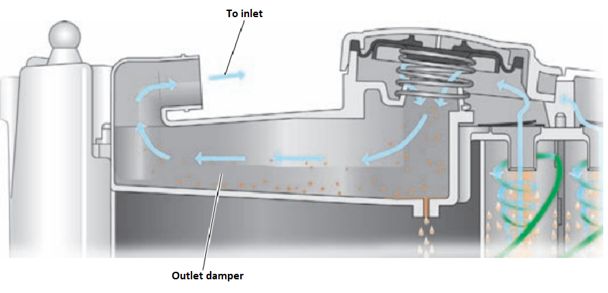
To prevent the formation of turbulence when the crankcase gases are introduced into the intake tract, the gases pass through an outlet stabilizer. In the exit still chamber, the flow of gases is freed from the vortices imparted to it by the centrifugal oil separators. In addition, some residual oil suspension is also separated in this chamber.
Cooling system
Forced circulation of liquid in the cooling system is created by a mechanical pump, which is driven from the crankshaft of the engine by a toothed belt. A thermostat with a solid filler installed in the cooling system switches the coolant circulation to a large or small circle.
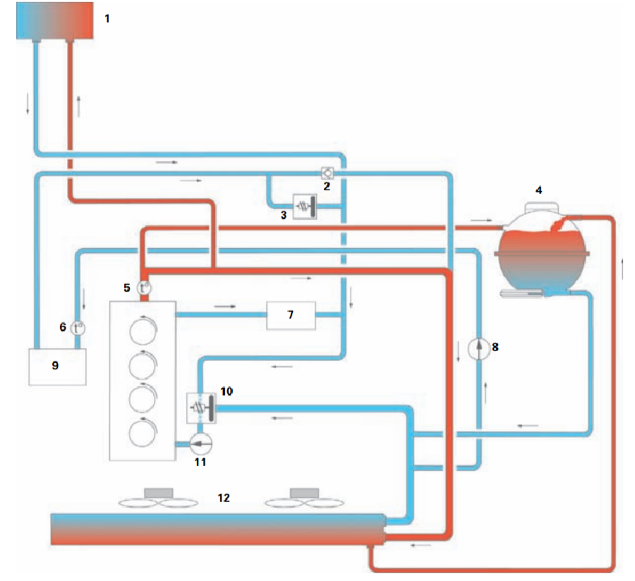
Components:
1. Heater heat exchanger.
2. Non-return valve.
3. Thermovalve.
4. Expansion tank.
5. Coolant temperature sensor G62.
6. Coolant temperature sensor at the outlet of the G83 radiator.
7. Oil radiator.
8. Radiator pump of the exhaust gas recirculation system V400.
9. Radiator of the exhaust gas recirculation system.
10. Thermostat.
11. Cooling system pump.
12. Radiator.
Low-temperature cooling of exhaust gases during recirculation
To reduce NOx emissions, the engine is equipped with low-temperature cooling of recirculated exhaust gases. Before the engine reaches operating temperature, the recirculated exhaust gas cooling circuit forms a separate circuit in the cooling system.
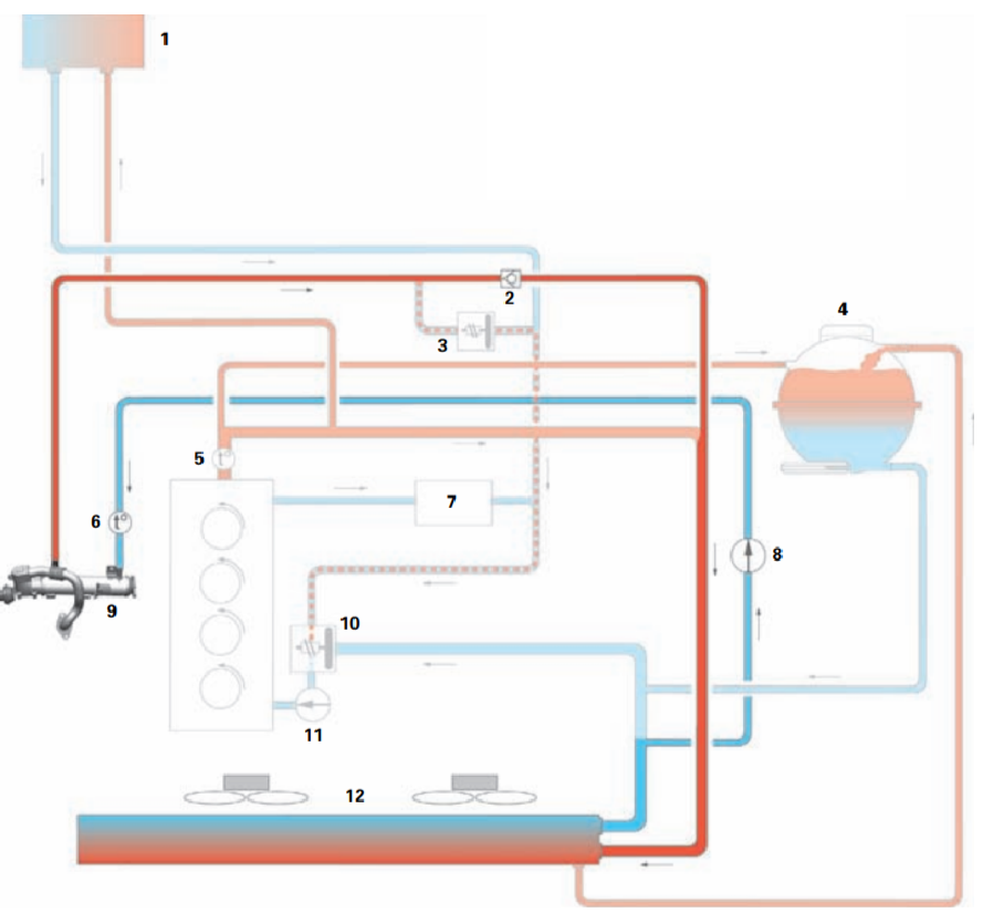
Working principle:
With the thermostat closed, the exhaust gas recirculation system radiator receives cooled coolant directly from the main cooling system radiator by means of the exhaust gas recirculation system radiator pump V400. Due to the cooling of recirculated exhaust gases to a sufficiently low temperature, a larger amount of them can be sent to the combustion chambers of the engine. This achieves a decrease in the combustion temperature and, as a result, a decrease in the content of nitrogen oxides in the exhaust gas during engine warm-up. An additional electric cooling system pump (V400 exhaust gas recirculation radiator pump) is controlled by the engine control unit and is always on when the engine is running. Starting at a temperature of approximately 70°C, the thermovalve opens and the non-return valve closes. The non-return valve prevents the occurrence of a counter current of coolant and, thereby, the formation of a "thermal jam" in the radiator of the exhaust gas recirculation system.
Radiator of the exhaust gas recirculation system
Cold engine
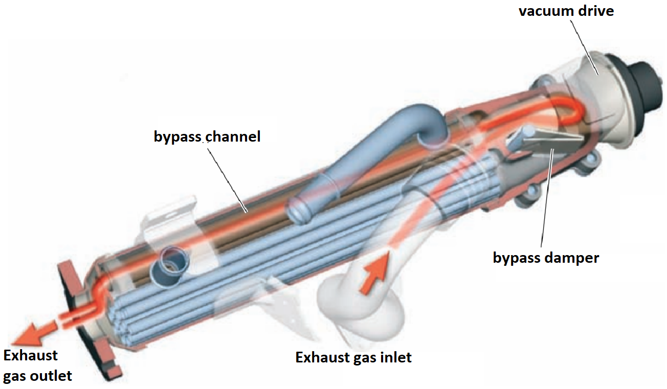
The bypass valve is open, and exhaust gases pass through the bypass channel, bypassing the radiator tubes. Hot exhaust gases contribute to faster reaching the working temperature and entering the working mode of the catalyst.
The engine is warm
At a temperature of approx. At 37°C, the bypass valve closes and exhaust gases begin to pass through the radiator tubes. Since the cooling liquid is supplied to the exhaust gas recirculation radiator directly from the main radiator of the cooling system, the recirculated exhaust gases enter the combustion chambers cooled. Cooler exhaust gases reduce the combustion temperature and thereby the formation of nitrogen oxides (NOx).
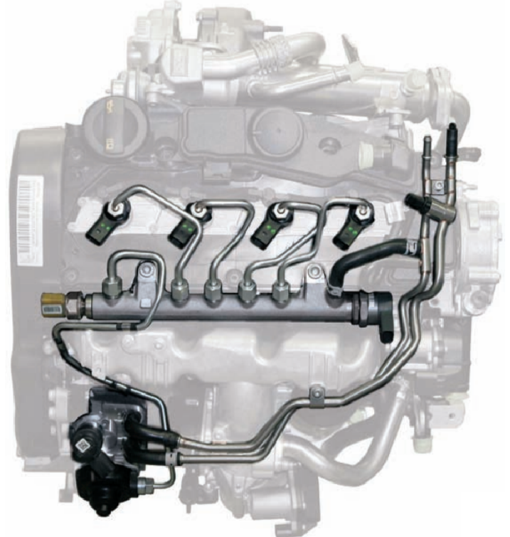
Common Rail injection system
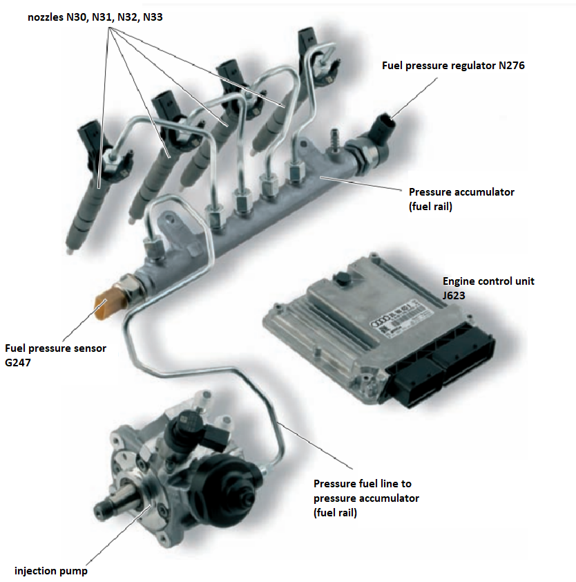
The power system of the new 2.0 l TDI engine uses a Common Rail injection system. The Common Rail injection system is a fuel injection system for diesel engines with a high-pressure accumulator. The English expression "Common Rail" literally means "common beam/ramp" and implies that fuel is supplied to each of the injectors from one common high-pressure accumulator. In such a system, the nodes that create high pressure and the nodes of the actual injection are separated. The high pressure of fuel required for injection is created by a high pressure pump (HPV). This pressure is stored in a high pressure accumulator (fuel rail) and is continuously supplied to each injector via short high pressure lines. The Common Rail injection system is controlled by the Bosch EDC 17 engine management system.
Fuel system (general scheme)
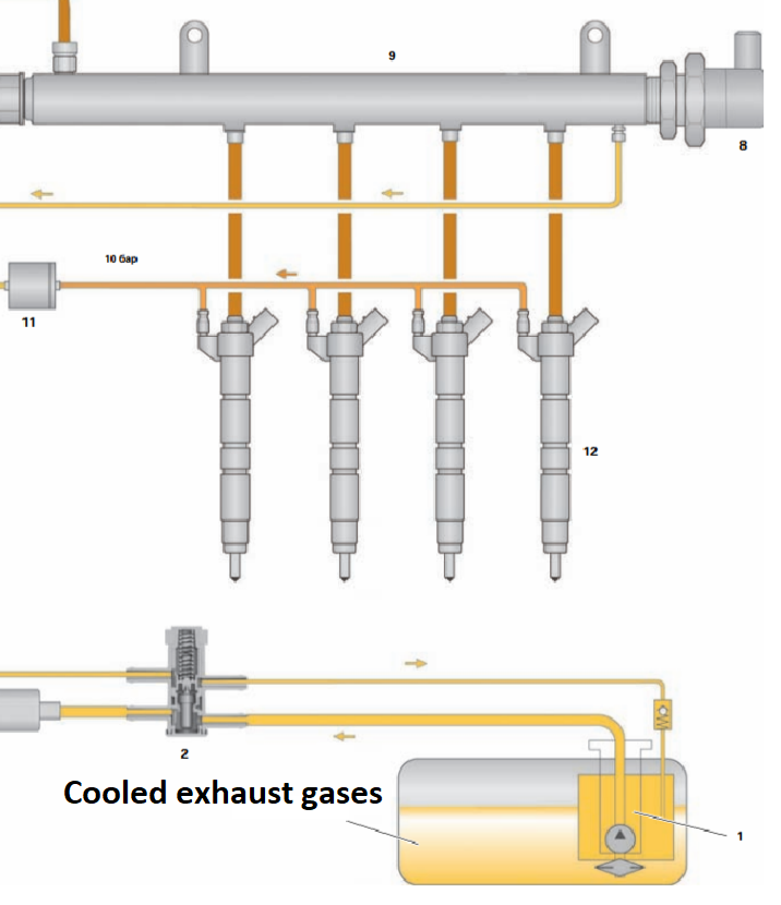
1. Fuel pump G6 pumping. Continuously supplies fuel to the pressure line.
2. Fuel preheating valve. Prevents clogging of the fuel filter with paraffins that crystallize at low temperatures.
3. Additional fuel pump V393. Delivers fuel from the pressure line to the fuel pump.
4. Fuel filter.
5. Fuel temperature sensor G81. Measures current fuel temperature.
6. High-pressure fuel pump (HPV). Creates the high pressure necessary for fuel injection.
7. Fuel metering valve N290. Adjusts the amount of fuel supplied to the high-pressure accumulator.
8. Fuel pressure regulator N276. Controls the fuel pressure in the high pressure circuit.
9. High-pressure accumulator (fuel rail). Serves as an accumulator of high pressure fuel required for injection for all engine cylinders.
10. Fuel pressure sensor G247 Measures current fuel pressure in the high pressure circuit.
11. Reducing valve. Maintains a constant residual pressure in the return lines of the injectors at the level of approximately 10 bar. This pressure is necessary for the normal operation of the nozzles.
12. Nozzles N30, N31, N32, N33.
Additional fuel pump
An additional fuel pump is installed in the area of the bottom, on the front right, and serves to supply fuel from the fuel tank to the pressure line of the injection pump. The auxiliary fuel pump is controlled by the engine control unit via a relay and increases the fuel pressure created by the electric fuel pump in the fuel tank by approximately 5 bar. This ensures uninterrupted fuel supply to the fuel injection pump in all engine operating modes.
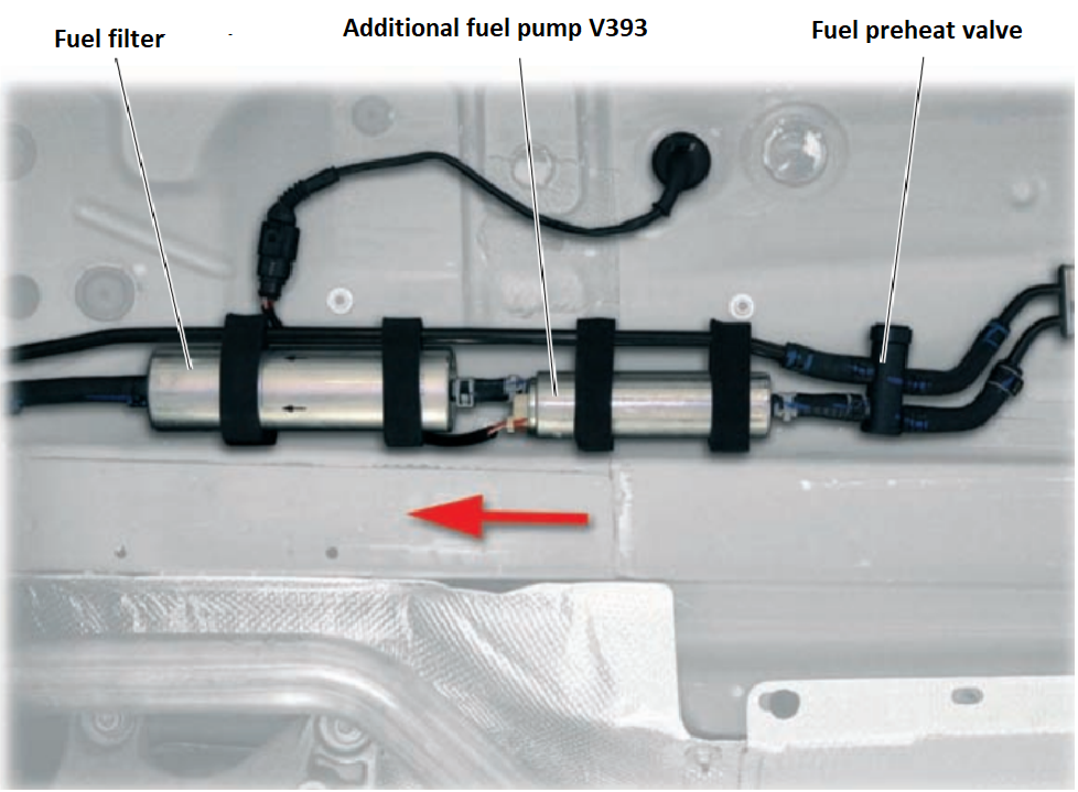
When malfunctions are detected in the operation of the additional fuel pump, the operation of the engine is impossible.
Optional V393 fuel pump and fuel filter
To protect the injection pump from impurities in the fuel (e.g. products of mechanical wear), a fuel filter is installed in the pressure line before the injection pump.
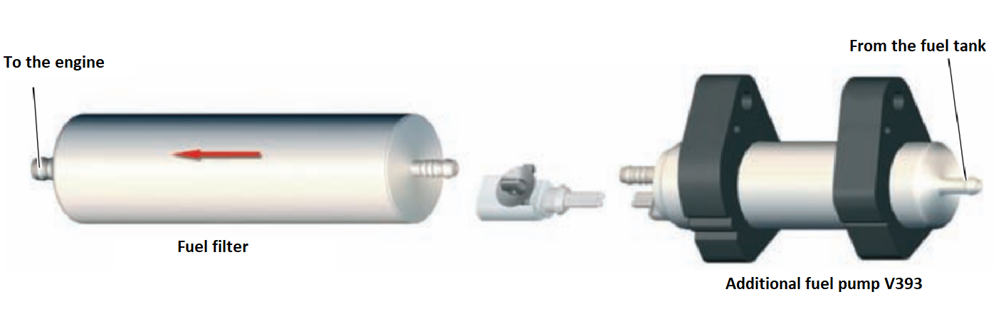
Fuel preheating valve
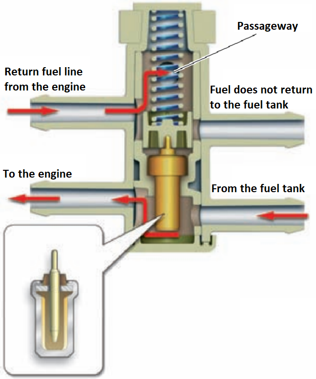
Previously, the fuel preheating valve was installed in the same unit as the fuel filter. The preheat valve controls fuel circulation in the low pressure circuit. On a cold engine, the thermocouple of the valve shortens and, through the spool, blocks the return fuel drain channel of the fuel tank. Returning from the engine, the warmer fuel is fed directly into the pressure line through the internal channel in the valve (bypassing the fuel tank). This warm fuel mixes with the cold fuel coming from the fuel tank and heats it, which prevents the fuel filter from clogging with paraffins at low air temperatures.
Cold fuel:
Control thermocouple
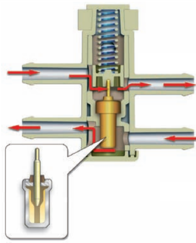
A thermocouple is a rigid metal container filled with a wax-like substance that expands upon melting. An increase in fuel temperature causes melting of the waxy filler and a significant increase in its volume. As a result, the filler squeezes out of the container a rod connected to a spool that opens the fuel return channel to the fuel tank. The opening temperature is approx. 15°C, rod stroke approx. 2 mm. When the fuel temperature decreases, the filler cools and decreases in volume, as a result of which the spool under the influence of the spring again blocks the channel to the fuel tank.
Warm fuel:
Technical features of the injection system
In any mode of engine operation, almost any fuel pressure optimal for this mode can be created.
High injection pressure, up to 1800 bar, ensures fine fuel atomization and good mixture formation.
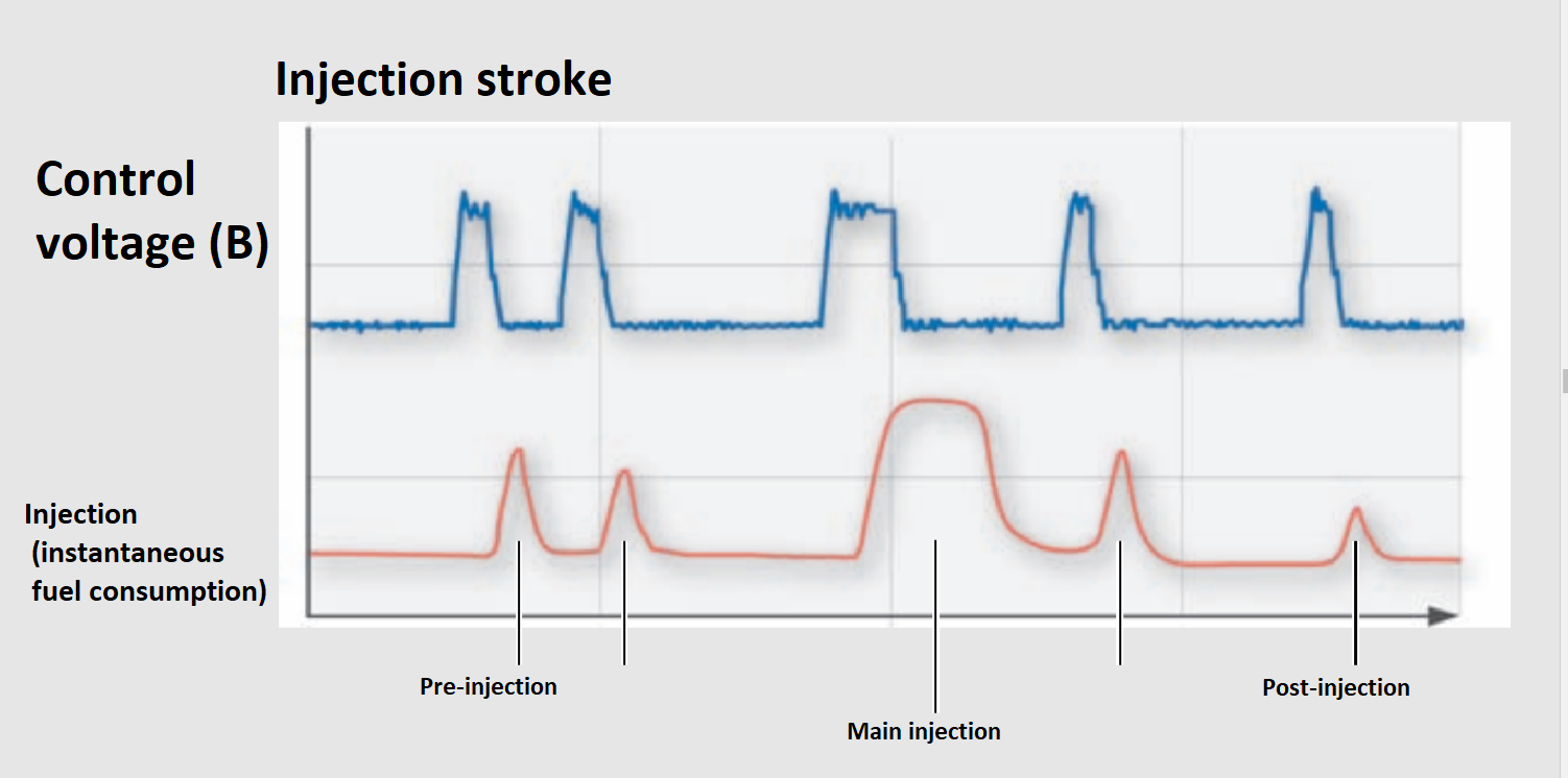
Flexible control of the injection process and the possibility of several previous and subsequent injections.
Due to a wide range of injection pressures and strokes, the Common Rail system provides ample opportunities to optimize the injection process in any of the engine's operating modes. Thus, it creates good prerequisites for meeting the ever-increasing requirements for power systems in terms of reducing fuel consumption, exhaust gas toxicity, and engine noise.
Injectors
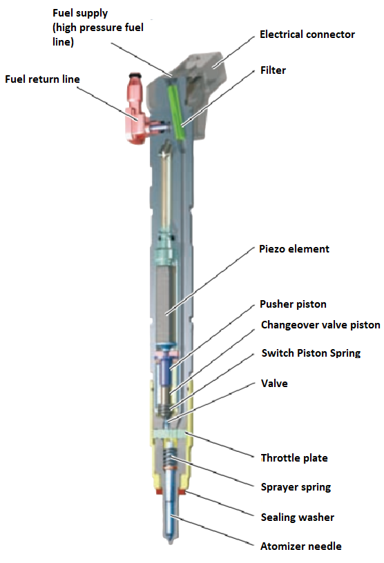
Piezo injectors are used in the Common-Rail system of the 2.0-liter engine. Active elements in such nozzles are piezo crystals. The operating speed of the piezo crystal actuator exceeds the operating speed of the electromagnetic valve by four times. In addition, the use of piezo technology allows to reduce the moving mass associated with the spray needle by 75% compared to electromagnetic nozzles.
This provides the following advantages to the system:
- very short switching time;
- the possibility of implementing several (up to 5) injections in one working stroke;
- exact dosage of the amount of injected fuel.
Fuel injection pump CP 4.1
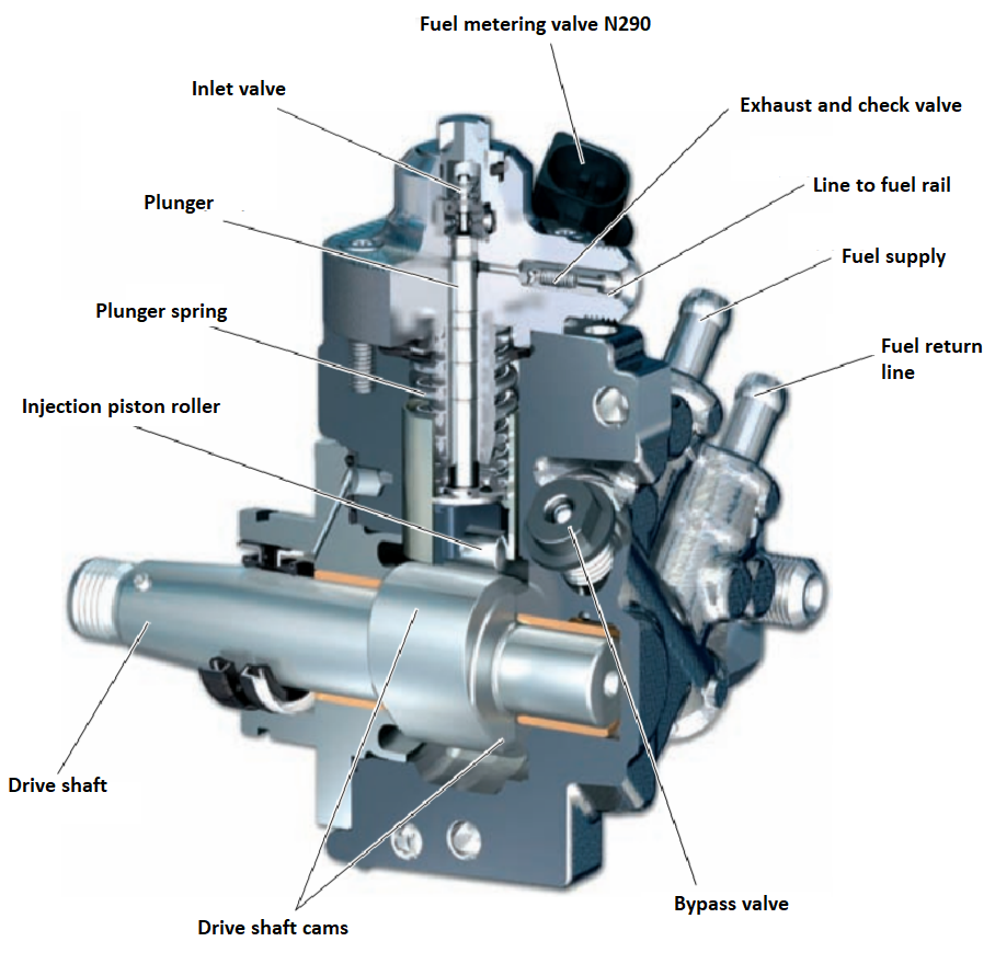
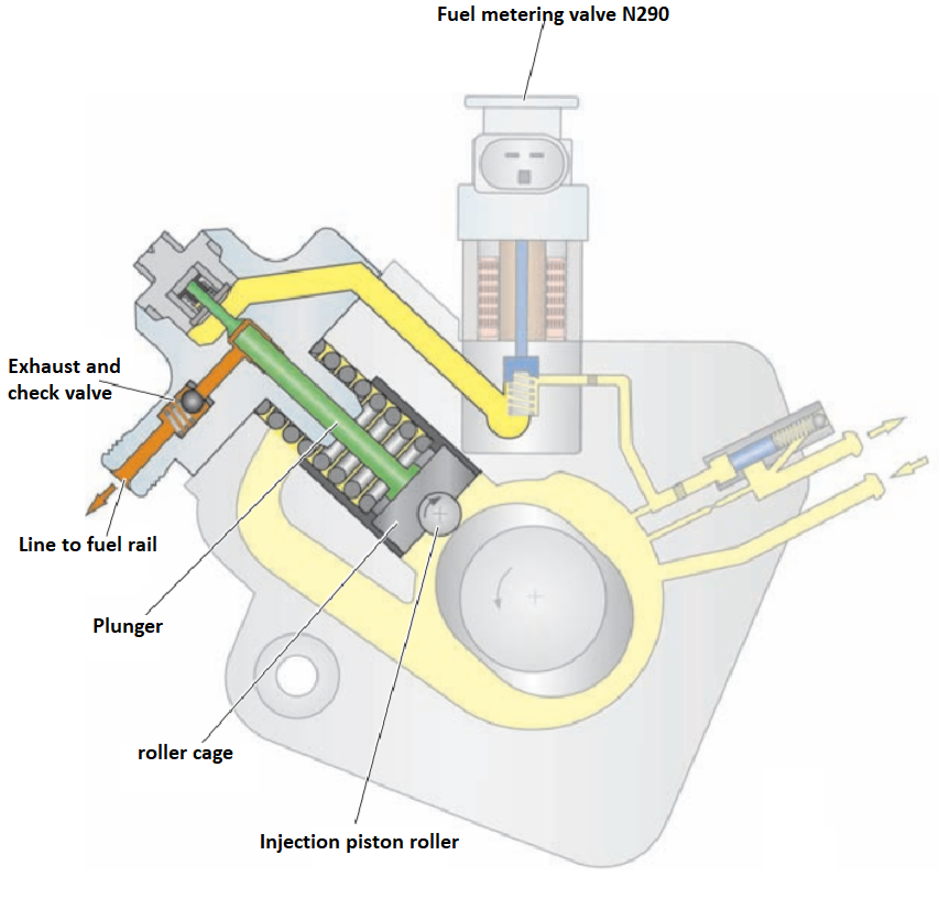
The injection pump of the new engine is made according to the single-plunger scheme. It is driven by a toothed belt from the engine crankshaft and rotates simultaneously with it. The injection pump creates the high fuel pressure required for injection, up to 1,800 bar. On the drive shaft of the pump there are two cams located diametrically (at 180° to each other), due to which the creation of high pressure always occurs during the compression stroke of the corresponding cylinder. Thanks to this, the load on the pump drive is evenly distributed, and pressure fluctuations in the high-pressure circuit are minimized.
Scheme of the device
High pressure zone
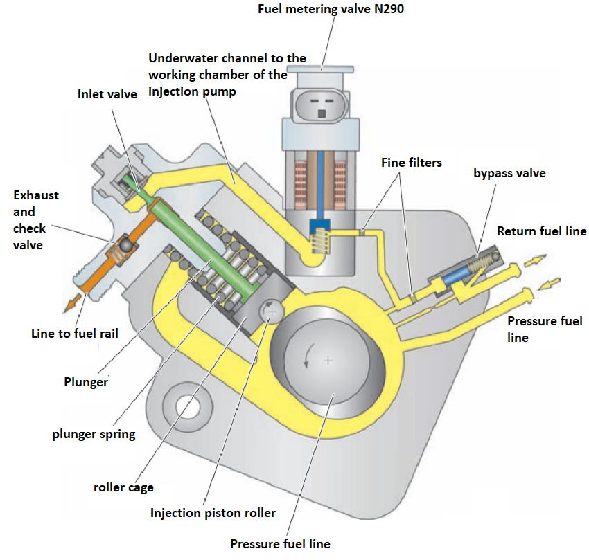
An additional fuel pump supplies a sufficient amount of fuel to the injection pump under a pressure of approx. 5 bar regardless of the engine operating mode. Through the fuel metering valve N290, fuel enters the high-pressure zone of the injection pump. The running cam of the drive shaft causes the pump plunger to move radially (up). A roller is installed in the lower part of the plunger in the clip to reduce frictional losses.
Admission
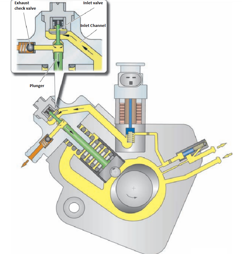
When the plunger under the influence of the spring moves down, the volume of the compression chamber of the injection pump increases. The pressure in the compression chamber becomes lower than in the supply channel, as a result of which the inlet valve opens and fuel begins to flow into the working area of the pump.
Work progress
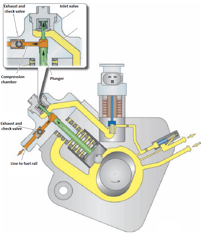
As the plunger begins to rise, the pressure in the compression chamber increases and the intake valve closes. When the pressure in the compression chamber becomes higher than the pressure in the high-pressure circuit, the exhaust valve (check valve) opens and fuel flows into the high-pressure accumulator (fuel rail).
Fuel Metering Valve N290
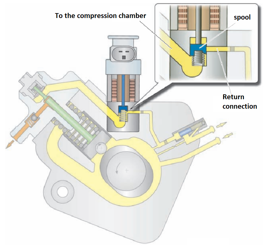
The fuel metering valve N290 is made as one unit with a high pressure pump. It controls the supply of fuel to the high-pressure circuit depending on the engine's needs. As a result of this control, the injection pump supplies the high-pressure accumulator with exactly as much fuel as the engine needs in the current operating mode, and no more. This reduces the power consumption of the injection pump and avoids unnecessary fuel heating.
Working principle:
The fuel metering valve N290 is normally open, that is, when no voltage is applied to it, it is open. To reduce the fuel supply to the compression chamber, the engine control unit sends a pulse-width modulation (PWM) signal to the valve. As a result of the PWM signal, the fuel metering valve N290 closes with a certain gap. Depending on the frequency of the signal, the position of the spool changes and thus the supply of fuel to the compression chamber of the injection pump.
When it fails, the engine power is reduced. Engine control works in emergency mode.
Low pressure zone
The bypass valve performs the function of fuel pressure regulation in the low pressure zone.
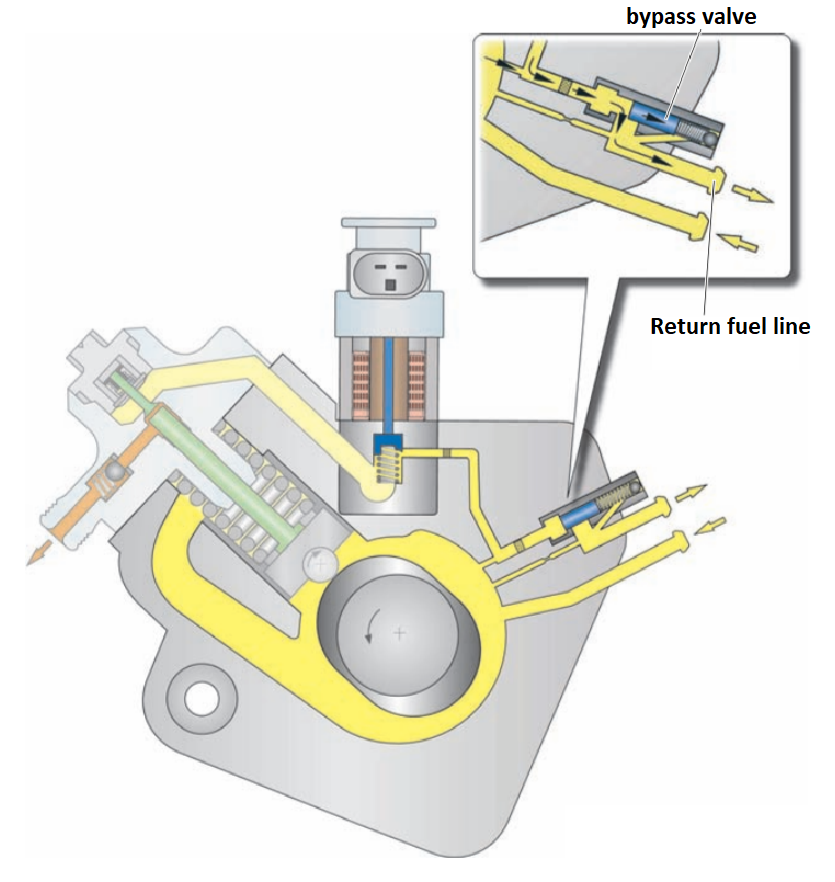
Working principle:
An additional fuel pump supplies fuel from the fuel tank to the pressure line (TNVD) under a pressure of approximately 5 bar. This ensures uninterrupted fuel supply to the injection pump in all engine operating modes. The bypass valve limits the internal pressure of the injection pump to approximately 4.3 bar. The fuel supplied by the auxiliary pump exerts pressure on the bypass valve spool (and spring). When the pressure exceeds 4.3 bar, the bypass valve opens fuel access to the return line. Excess fuel supplied through the pressure line is returned to the fuel tank through the return line.
Fuel rail pressure control
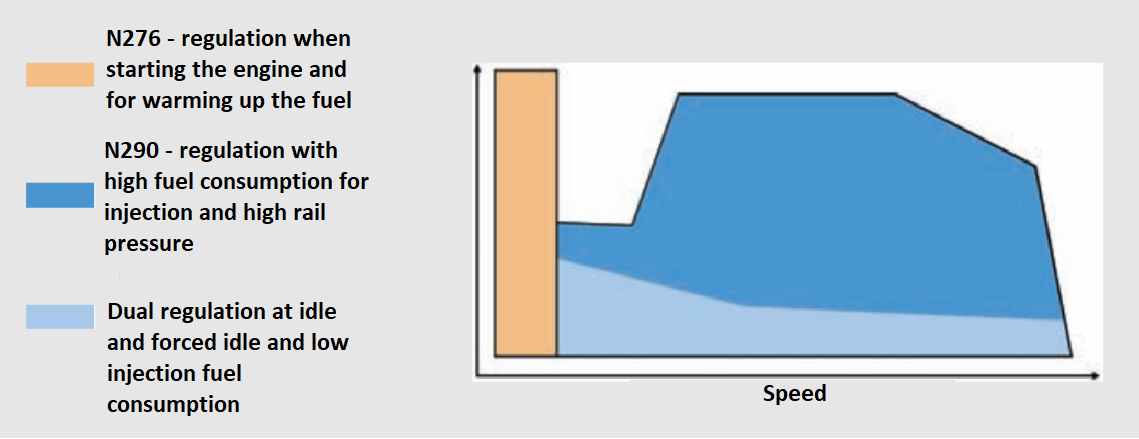
In the Common Rail injection system of the 2.0 L TDI-CR engine, the so-called dual regulation concept. Depending on the engine operating mode, the high fuel pressure is regulated either by the N276 fuel pressure regulator in the fuel rail or by the N290 fuel metering valve in the injection pump. For this, the engine control unit sends the corresponding PWM signal to the specified valves.
Regulation with the help of fuel pressure regulator N276
When starting the engine and for warming up the fuel, the high pressure is regulated by the fuel pressure regulator N276. To accelerate fuel heating, the injection pump supplies more fuel to the fuel rail, and thus to the high-pressure zone, than is necessary for the engine to work. Excess fuel through the open fuel pressure regulator N276 is returned to the low pressure circuit.
Adjustment with the fuel metering valve N290
If a large amount of fuel is required for injection and a high pressure of the fuel rail, the pressure is regulated by the fuel metering valve N290. Thus, exactly as much fuel as the engine needs in the current mode of operation is supplied to the fuel rail. This reduces the power consumption of the injection pump and avoids unnecessary fuel heating.
Adjustment with the help of both valves
In idle or forced idle mode, as well as with low fuel consumption for injection, high pressure is regulated by both valves. In this way, high accuracy of pressure regulation is achieved, which is necessary for stable operation at idle speed, reducing exhaust gas toxicity and ensuring a smooth transition to forced idle mode.
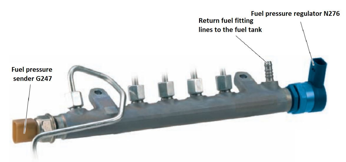
Fuel pressure regulator N276
The fuel pressure regulator N276 is installed in the high-pressure accumulator (fuel rail). The required amount of pressure in the fuel rail is set by opening and closing the regulator valve. For this, a PWM signal is sent to the N276 fuel pressure regulator from the engine control unit.
Construction:
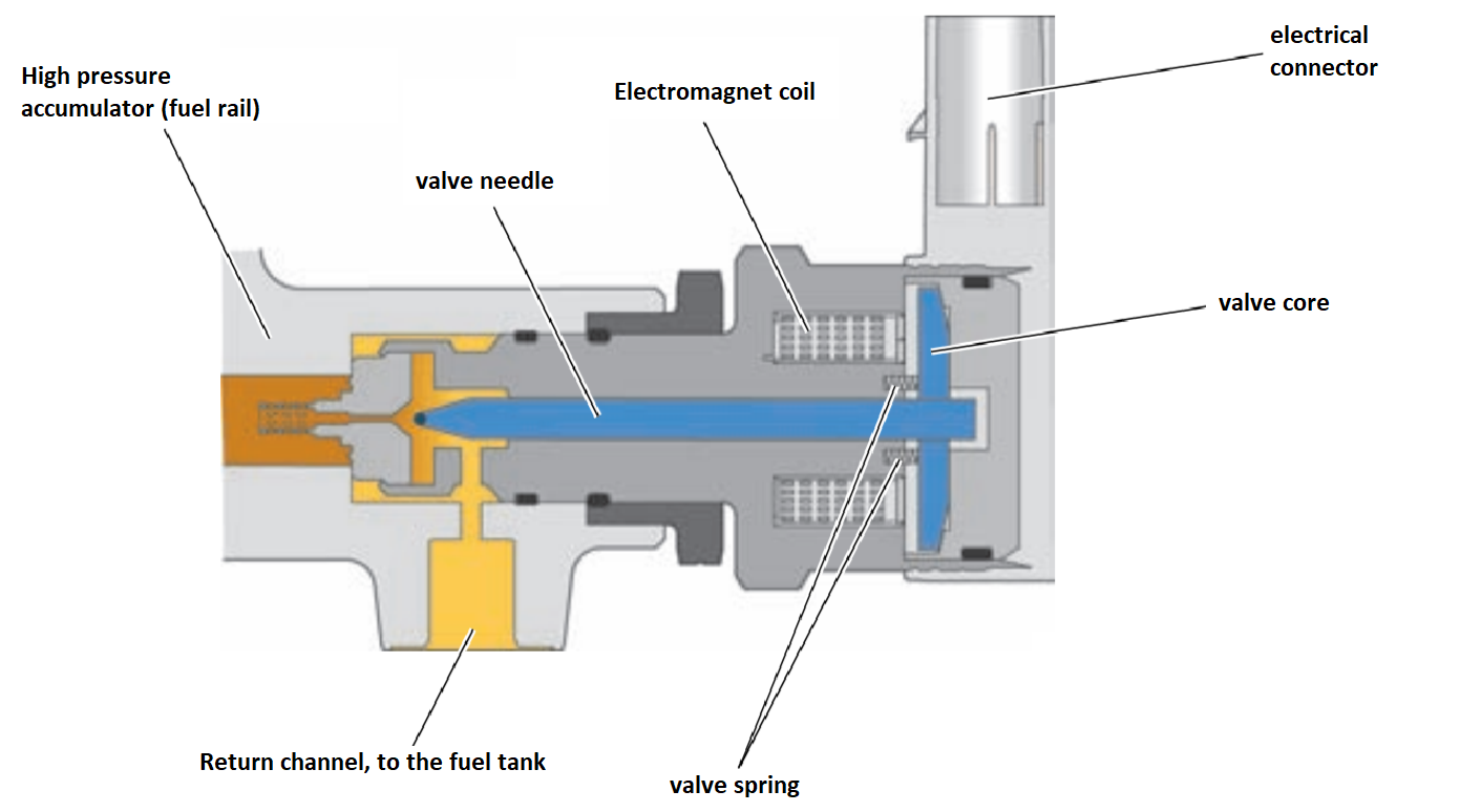
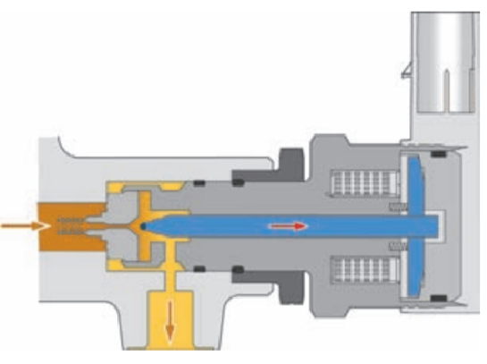
'Regulator in free state (engine off)
If no control signal is applied to the regulator, its valve is open under spring pressure. The fuel rail connects to the return line. This ensures communication between high and low pressure areas. It prevents the formation of bubbles of fuel vapors, which could occur in the fuel rail when the fuel cools after the engine has stopped, and thus facilitates the subsequent start of the engine.
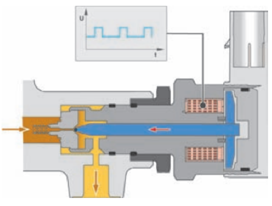
A control signal is applied to the regulator (the engine is on)
To set the required working pressure in the fuel rail in the range from 230 to 1800 bar, the control unit of the diesel injection system. engine J248 supplies a pulse-width modulated signal (PWM signal) to the regulator. As a result, a magnetic field arises in the valve's electromagnetic coil. The core is attracted to the coil and thereby presses the valve needle to the seat. Thus, the fuel pressure in the ramp acts against the magnetic attraction of the core. By changing the frequency of the supplied signal, you can change the cross-section of the valve and thus the amount of fuel entering the return line. In addition, this scheme allows you to smooth out pressure fluctuations that occur in the fuel rail.
When the N276 pressure regulator fails, engine operation is not possible because it is not possible to create a fuel rail pressure high enough to inject fuel.
Sensors
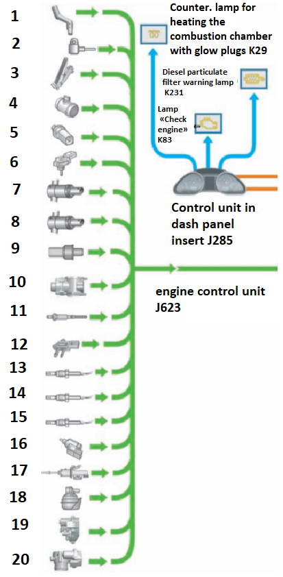
Engine speed sensor G28 - 1
Hall sensor G40 - 2
Accelerator pedal position sensor G79 - 3
Air flow meter G70 - 4
Coolant temperature sensor G62 - 5
Boost pressure sensor G31 - 6
Intake air temperature sensor G42 - 7
Coolant temperature sensor at the outlet of the radiator G83 - 8
Fuel temperature sensor G81 - 9
Fuel pressure sensor G247 - 10
Potentiometer of the exhaust gas recirculation system G212 - 11
Lambda probe G39 - 12
G450 exhaust gas pressure sensor 1 - 13
Exhaust gas temperature sensor 1 G235 - 14
Exhaust gas temperature sensor 4 G648 - 15
Clutch pedal position sensor G476 - 16
Boost pressure regulator position sensor G581 - 17
G336 inlet valve position sensor - 18
Throttle potentiometer G69 - 19
Exhaust gas temperature sensor 3 G495 - 20
Brake light switch F - 21
Engine control system
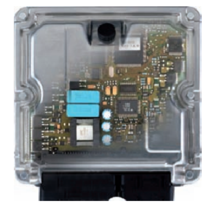
To control the 2.0 L TDI-CR engine, the EDC 17 electronic diesel engine control system manufactured by Bosch is used. The EDC 17 engine management system is a further development of the EDC 16 system. The main differences from the EDC 16 system are increased processor power and increased memory capacity.
CAN bus interfaces (CAN drive)
The following messages are forwarded by the CAN drive bus control units. The total number of possible messages is very large, and the following list shows only some of the most important ones.
J533 data bus diagnostic interface (internet interface):
- Adaptive cruise control (ACC) system information.
- Increasing the number of idling revolutions.
- Mileage in km.
- Date.
- Time.
- Stop signal.
- Trailer recognition.
- Cruise control information (GRA).
- Oil level and temperature information.
- Generator load.
- Audi drive select information.
- Lane keeping assistant information.
- Electromechanical parking brake.
ABS control unit J104:
- ASR request.
- ABS request.
- EDS request.
- ESP intervention.
- ESP brake light switch.
- Speed signal.
- Moment of MSR intervention.
- Transverse acceleration.
- Wheel rotation speed.
- ASR intervention moment.
Automatic control unit J217:
- Toggle active/inactive.
- Air conditioner compressor.
- Off..
- The condition of the torque converter.
- Transmission to include.
- The position of the selector lever.
- Engine torque.
- Coefficient of movement resistance (on climbs).
- Emergency programs (information about self-diagnosis).
- OBD2 status.
- The frequency of rotation of the turbine wheel.
- Nominal number of idling revolutions.
G85 steering wheel angle sensor:
Steering wheel angle (used to control the idle speed controller (as feedback) and calculate engine torque (determines the power used by the power steering)).
Engine control unit J623:
- Information on idle speed (MSR).
- Information on operation in the intensive acceleration mode (Kick-Down).
- Clutch pedal switch.
- The number of revolutions of the crankshaft.
- Engine torque.
- Coolant temperature.
- Information about the status of the brake light switch.
- Brake pedal switch.
- Cruise control switch position.
- Set cruise control speed.
- The number of idling revolutions.
- Pre-heating system message.
- Throttle opening angle.
- Intake air temperature.
- OBD2 on-board diagnostics lamp.
- Temperature control lamp.
- Coolant temperature.
- Fuel consumption.
- Radiator fan control.
- Air conditioner compressor.
- Load shedding or power reduction.
- Soot filter control lamp.
- Start-up management.
- Interlock switch.
- Removing the starter lock.
- Shutting down the starter.
- Oil temperature.
- Boost pressure adjustment.
- Audi drive select information.
- Upshift or downshift recommendation.
- Maintenance interval counter (WIV) information.
- Gearbox coding.
Turbocharger
The 2.0L TDI-CR engine uses a variable geometry turbocharger to create boost pressure. In it, the flow directed to the impeller of the OG turbine is controlled by turning the guide vanes. This allows you to ensure optimal supercharging pressure and thus good combustion in the entire range of revolutions. Changing the position of the guide vanes allows you to achieve high torque and good acceleration from a standstill in the lower rev range, and lower fuel consumption and exhaust gas toxicity in the upper rev range. The rotation of the guide vanes is carried out by a vacuum drive through a rod.
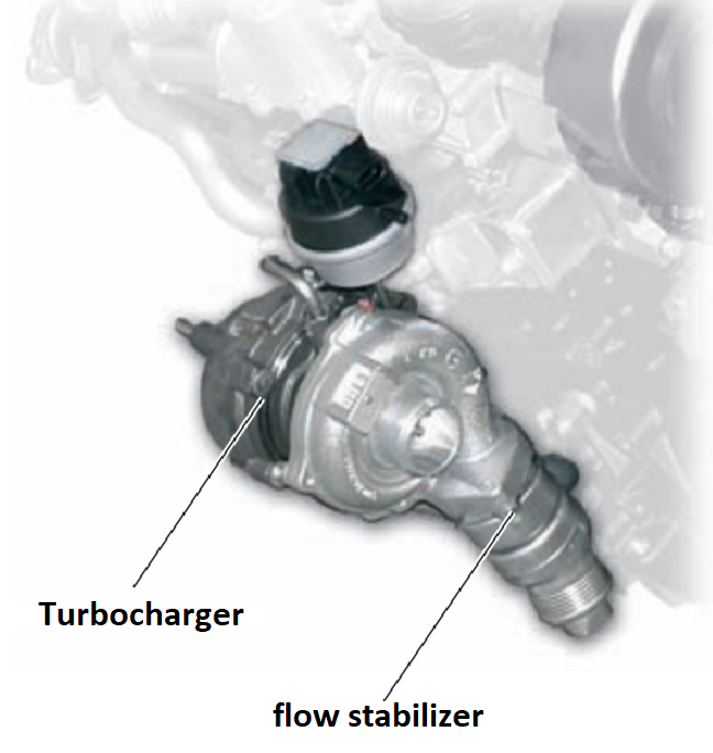
Air flow retarder
A flow stabilizer made of stainless steel is installed at the outlet of the turbocharger. It is designed to reduce unwanted turbocharger noise.
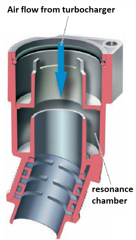
Device and principle of action:
When acceleration with maximum acceleration is necessary, the turbocharger must create boost pressure as quickly as possible. At the same time, the turbine and pump wheels accelerate to high speeds, and the turbocharger operates in a mode close to the limit. This leads to rapids in the air flow and, as a result, to the formation of unwanted noises that spread through the supercharged air path. The passage of supercharged air causes the air in the still chambers to oscillate. These oscillations approximately coincide in frequency with the noise of supercharged air. As a result of the interference, the sound waves of supercharged air noise and vibrations from the stilling chambers partially cancel each other, leading to a reduction in noise.
Boost pressure adjustment
Boost pressure is regulated by changing the amount of air supplied/compressed by the turbocharger.
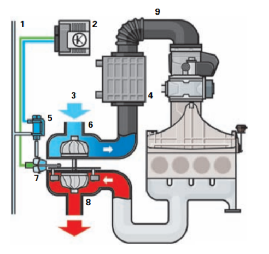
Legend:
1 - Vacuum line.
2 - Engine control unit J623.
3 - Air is sucked in.
4 - Intercooler.
5 - Solenoid valve for limiting boost pressure N75.
6 - The pumping part of the turbocharger.
7 - Vacuum drive.
8 - Turbine with variable geometry.
9 - Boost pressure sensor G31,
G42 intake air temperature sensor.
Boost pressure limiting solenoid valve N75
The N75 boost pressure limiting solenoid valve is an electro-pneumatic actuator. The electromagnetic valve controls the supply of vacuum to the vacuum drive, which, in turn, changes the position of the guide vanes of the turbine.

Boost pressure sensor G31/ intake air temperature sensor G42
The supercharging pressure sensor G31 and the air temperature sensor at the inlet G42 are made as a single unit, which is installed in the supercharged air pipe in front of the air damper.
G42 intake air temperature sensor
The G42 intake air temperature sensor signal is used by the engine control unit to regulate boost pressure. Since its density depends on the temperature of the air, the signal is used by the engine control unit to enter the corresponding amendments
Boost pressure regulator position sensor G581
The boost pressure regulator position sensor G581 is built into the vacuum drive of the turbocharger. It is a displacement sensor and gives the BO engine information about the actual position of the guide vanes. Together with the boost pressure sensor signal, G31 allows you to infer the current state of the boost control.
Exhaust gas recirculation
Exhaust gas recirculation is necessary to reduce emissions of nitrogen oxides from exhaust gas. The operation of the exhaust gas recirculation system consists in feeding part of the exhaust gas back into the intake tract and thereby the combustion chamber of the engine. This causes a decrease in the oxygen content in the fuel-air mixture and, as a result, a slowdown in the combustion process. As a result, the maximum combustion temperature decreases and emissions of nitrogen oxides decrease.
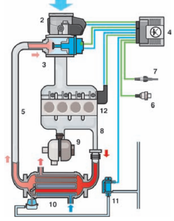
Components:
1 - Suction air.
2 - Throttle block J338 with throttle potentiometer G69.
3 - Exhaust gas recirculation valve with exhaust gas recirculation system potentiometer G212 and exhaust gas recirculation valve N18.
4 - Engine control unit J623.
5 - Recirculated exhaust gas supply line.
6 - Coolant temperature sensor G62.
7 - Lambda probe G39.
8 - Exhaust manifold.
9 - Turbocharger.
10 - Radiator of the exhaust gas recirculation system.
11 - Radiator switch of the exhaust gas recirculation system N345.
12 - V157 air damper electric motor with G336 inlet damper potentiometer.
The amount of recirculated exhaust gas is regulated according to the multi-parameter characteristics laid down in the engine's BO. It takes into account such parameters as the crankshaft speed, the amount of fuel injected, the mass and temperature of the incoming air, and the boost pressure. A broadband lambda probe is installed in the exhaust tract before the soot filter. This probe allows you to determine the content of OG oxygen in a wide range of measurements. The exhaust gas recirculation system uses the lambda probe signal to correct the amount of exhaust gas being recirculated. The cooling radiator in the exhaust gas recirculation system allows you to lower the temperature of the recirculated gases, and thereby further reduce the combustion temperature, as well as increase the amount (mass) of recirculated exhaust gas. This effect is further enhanced by the low-temperature cooling scheme of recirculated exhaust gases.
Exhaust gas recirculation valve N18
The movement of the N18 exhaust gas recirculation valve plate is carried out with the help of an executive electric motor. It is controlled by the engine control unit and can guide the valve plate to any intermediate position. By moving the valve plate, the amount of recirculated exhaust gases is regulated.
Potentiometer of the exhaust gas recirculation system G212
The G212 exhaust gas recirculation system potentiometer determines the current position of the exhaust gas recirculation valve plate. With the help of this signal, the engine control unit receives information about the actual position of the valve plate. It is used to regulate the amount of recirculated gases, and thereby the content of nitrogen oxides in the exhaust gas.
Radiator switch of the exhaust gas recirculation system N345
The radiator of the exhaust gas recirculation system can be switched on or off. Thus, the engine and soot filter can warm up to operating temperature faster. The radiator of the exhaust gas recirculation system switches to cooling mode, starting from the coolant temperature approx. The daytime air temperature is 37°C. The radiator switch of the exhaust gas recirculation system N345 is electro-pneumatic. The movement of the bypass valve of the radiator is carried out with the help of a vacuum drive, the supply of vacuum to which is controlled by an electromagnetic valve.
Failure of the switching valve makes it impossible to move the bypass valve with a vacuum drive. The damper closes the bypass channel, and the radiator constantly works in cooling mode. As a result, it takes longer for the engine and particulate filter to reach operating temperature.
Throttle block J338
Throttle block J338 is installed in front of the exhaust gas recirculation valve (in the direction of air flow). The J338 throttle assembly has an executive electric motor that drives the throttle through the gearbox. The throttle position is continuously adjustable and can be optimized for any combination of load and engine speed. Throttle assembly J338 serves for the following. In certain operating modes, the throttle creates a pressure difference between the intake tract and the exhaust gas recirculation tract. Thanks to this pressure difference, effective exhaust gas recirculation is achieved. In the regeneration mode of the particulate filter, the throttle valve controls the flow of air entering the cylinders. When the engine is turned off, the flap closes. As a result, less air enters and is compressed into the engine cylinders, thanks to which the engine stops more smoothly.
In the event of failure, proper management of exhaust gas recirculation becomes impossible. Active regeneration of the soot filter is not performed.
Throttle potentiometer G69
Throttle potentiometer G69 is built into the throttle actuator. A sensitive element of the sensor determines the current position of the throttle valve.
With the help of this signal, the engine control unit receives information about the actual position of the throttle valve. These data are used in the management of exhaust gas recirculation and particulate filter regeneration.
In the event of failure, exhaust gas recirculation is disabled, active regeneration of the soot filter is not performed.
Soot filter
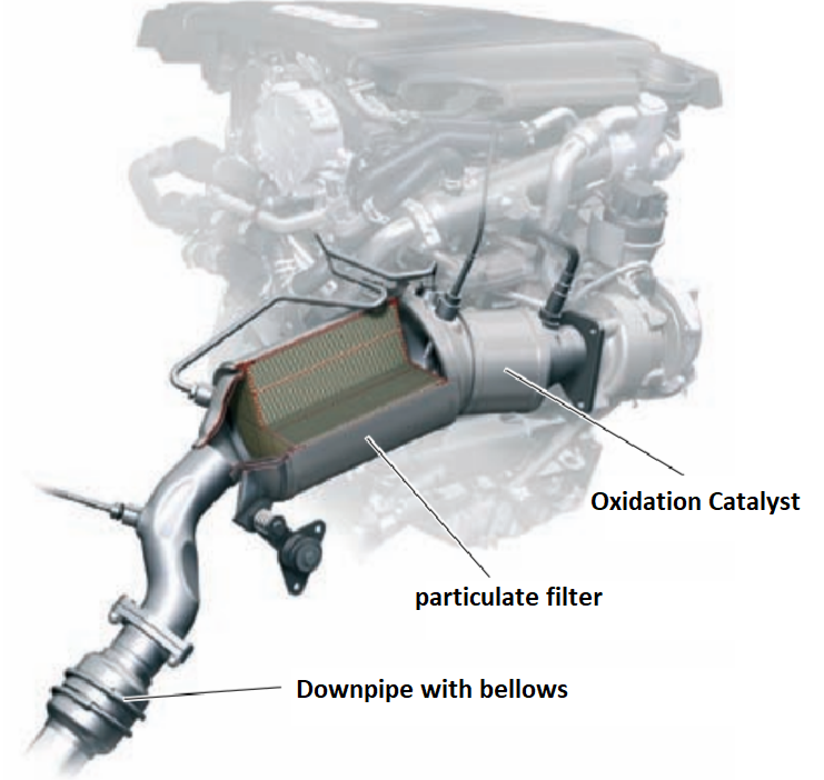
To reduce the formation of soot particles on the 2.0 l TDI-CR engine, in addition to internal measures, a soot filter is used. The soot filter is installed after the catalyst. Both units are installed in a common housing in close proximity to the engine to reach operating temperature more quickly.
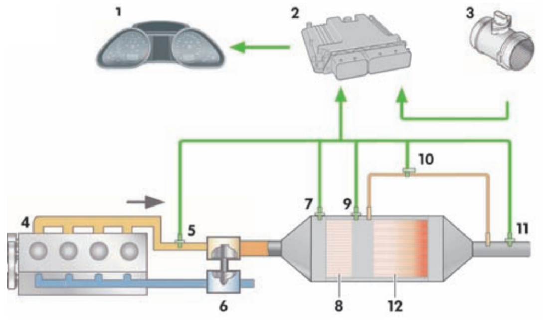
Components:
1 - Instrument cluster control unit J285.
2 - Engine control unit J623.
3 - Air flow meter G70.
4 - Diesel engine.
5 - Exhaust gas temperature sensor 1 G235.
6 - Turbocharger.
7 - Lambda probe G39.
8 - Oxidizing catalyst.
9 - Exhaust gas temperature sensor 3 G495.
10 - G450 exhaust gas pressure sensor 1.
11 - Exhaust gas temperature sensor 4 G648.
12 - Soot filter.
Construction of a particulate filter
The soot filter and the oxidation catalyst are two separate units located in the common housing. At the same time, the catalyst is installed in front (in the direction of the gas flow) of the soot filter.
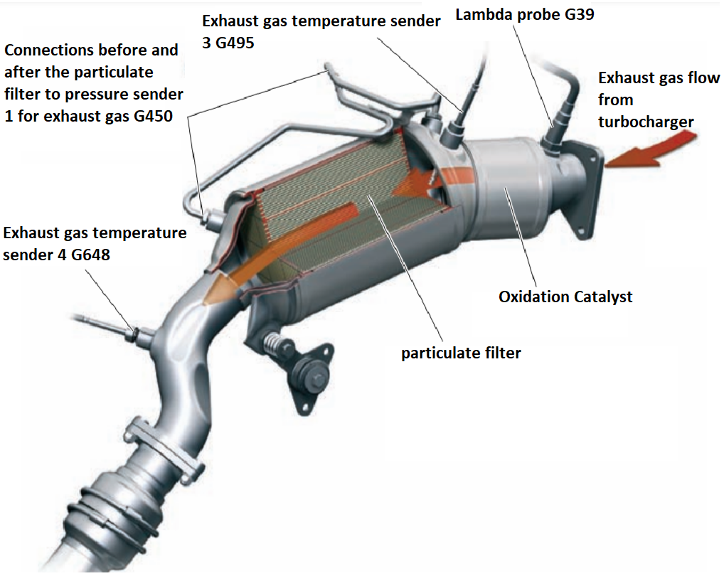
Installation in one unit with an oxidation catalyst has, together with the Common Rail injection system, the following advantages:
– The possibility of more precise regulation of the exhaust gas temperature during regeneration compared to a soot filter with catalytic spraying. The heat released in the catalyst as a result of the oxidation of hydrocarbons and carbon monoxide is taken into account immediately before the soot filter using a temperature sensor. This allows more accurate calculation of the amount of fuel that must be injected in the final phase of combustion ("post-injection") to increase the exhaust gas temperature during filter regeneration.
– Great safety during the restoration of the diesel filter.
– In the mode of forced idling, excessive cooling of the soot filter is prevented as a result of the inflow of cold air, the oxidation catalyst plays the role of a "heat accumulator".
Oxidizing catalyst
The catalyst has a metal carrier, which accelerates its heating to operating temperature. A coating of aluminum oxide is applied to the honeycombs of the carrier, on top of which a thin layer of platinum is deposited, as a catalyst for the oxidation of hydrocarbons (HC) and carbon monoxide (CO).
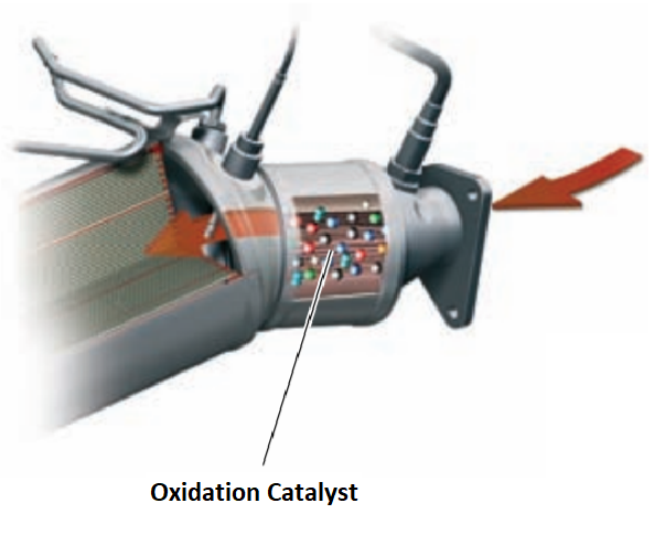
An oxidation catalyst converts most of the hydrocarbons (HC) and carbon monooxide (CO) into tent vapor and carbon dioxide (carbon dioxide).
Soot filter
The filtering element of the soot filter is a porous ceramic monolithic carrier made of silicon carbide. This ceramic medium has many parallel microchannels. The channels are alternately blocked by partitions from the input or output side. That is, these are inlet and outlet channels separated by filter walls. The filtering walls have a porous structure and are covered with a bearing layer of aluminum oxide (and zirconium dioxide). A platinum coating, which serves as a catalyst, is sprayed on this supporting layer.

Exhaust gases containing soot particles enter the inlet channels with porous walls. At the same time, exhaust gases pass through the porous walls into the outlet channels, while parts of the soot remain in the intake channels.
Regeneration:
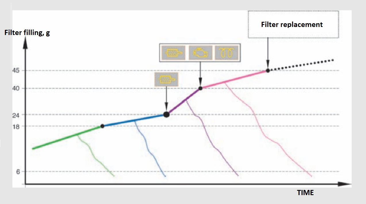
With prolonged use, the soot filter becomes clogged with soot particles and loses its effectiveness. To maintain efficiency, the soot filter must undergo regular regeneration. During the regeneration process, soot particles collected in the filter are burned.
Particulate filter regeneration can take different forms:
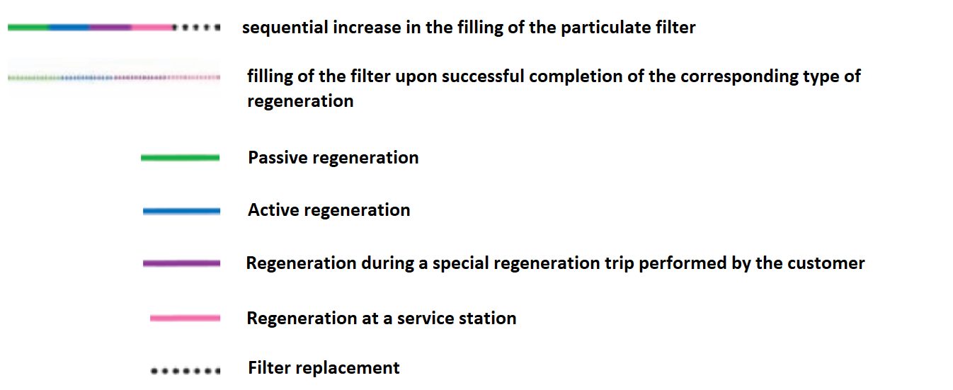
passive regeneration,
heating phase,
active regeneration,
regeneration during a special regeneration trip performed by the customer,
regeneration performed by the maintenance service.
Heating phase:
In order to heat the catalyst and the soot filter as quickly as possible and thereby bring them to operating temperature, the engine control system performs additional fuel injection after the main one. Additional fuel burns in the cylinder and thus increases the combustion temperature. The additional heat released at the same time is carried by the exhaust gases to the catalyst and the particulate filter, heating them. The heating phase ends as soon as the catalyst and the soot filter have heated up to the operating temperature and have maintained it for a certain time.
Passive regeneration:
During passive regeneration, soot particles are constantly burned without an engine control system. This happens mainly when the engine is working with a high load, for example, when driving on a high-speed highway, at exhaust gas temperatures of 350°C 500°C. At the same time, soot particles are transformed into carbon dioxide by a chemical reaction with nitrogen dioxide.
Active regeneration:
In the vast majority of normal operating modes, the exhaust gas temperature is insufficient for passive regeneration. Since the combustion of soot particles does not occur, these particles accumulate in the filter. When a certain amount of soot accumulates in the filter, the engine management system starts an active regeneration procedure. Soot particles are burned at an exhaust gas temperature of 600-650°C, turning into carbon dioxide.
The degree of filling and types of regeneration of the soot filter of the 2.0 L TDI-CR engine
Preheating system
The 2.0 l TDI-CR engine is equipped with a system of accelerated heating of the combustion chambers before starting. It provides a quick "gasoline" start of the engine in almost any climatic conditions without a long wait for the combustion chambers to warm up.
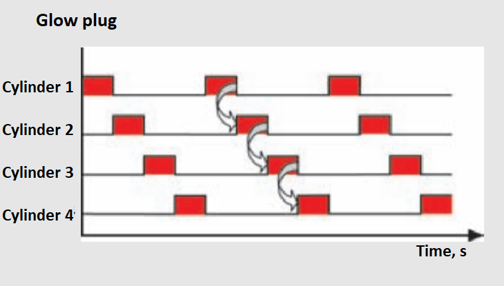
The steel glow plugs are controlled by the engine BO J623 through the glow plug BO J179 using phase-shifted PWM signals. At the same time, the voltage on individual glow plugs is set by changing the frequency of the supplied PWM pulses. For quick engine start at temperatures below 25°C, pre-heating is performed with a voltage of 11.5 V. This ensures the heating of the glow plug in the shortest time (max. 2 seconds) to a temperature of 1000°C. Thus, the preheating time of the combustion chambers is reduced.
Control signals of glow plugs with a phase shift
To prevent excessive load on the on-board network during pre-glow, the signals of individual glow plugs are supplied with a phase shift. At the same time, the falling edge of the signal of one candle always includes the corresponding candle.