4MOTION all-wheel drive with Haldex clutch model year 2004
AvtoAd
07/10/2022
Content
3. Syncro drive with viscous coupling .
4. 4MOTION drive with Haldex coupling of the first generation .
5. General instructions .
6. All-wheel drive 4MOTION Golf car model 2004.
7. All-wheel drive 4MOTION Transporter model 2004.
8. Angular transmission of the Golf model of 2004.
9. Angular transmission with an intermediate shaft of a 2004 model Transporter car.
10. Transmission of power through the transmission of a 2004 Golf car.
11. Transmission of power through the transmission of a 2004 model Transporter car .
12. Cardan shaft. Golf car model 2004 .
13. Transporter car model 2004.
14. Haldex clutch.
15. New elements in the Haldex coupling of the 2004 model year.
16. Details and assemblies of Haldex clutches of the 2004 model year.
17. Rear axle reducer. Golf car model 2004.
18. Transporter car model 2004.
20. Conditions for turning on the Haldex clutch of the 2004 model year.
21. Principle of operation of the Haldex clutch.
22. Parts and assemblies of Haldex clutch model year 2004.
23. The mechanical part of the clutch.
24. Details of the hydraulic system.
25. Hydraulic circuit .
26. Hydraulic accumulator .
27. Safety valve .
28. Inlet valves .
29. Clutch control system. Sensors.
30. Clutch control system. Executive devices.
31. Electrical and electronic components.
32. All-wheel drive control unit (J492).
33. Sensors located in the housing of the Haldex clutch .
34. Haldex clutch electric pump (V181).
35. Clutch control pressure regulator (N373).
36. Clutch control.
37. Processes in the control system when the ignition is turned on.
38. Processes in the control system at full engine load.
39. Processes in the control system when the engine is idling.
40. Processes in the control system at partial engine loads.
general information
Full drive
All-wheel drive on Volkswagen cars has a long tradition, if you do not even take into account the Iltis model and cars with air-cooled engines. In the development process, a transition was made from the Syncro drive with a viscous coupling to the 4MOTION drive with a Haldex coupling. The last time a viscous coupling was installed on a Transporter car of the previous model. All-wheel drive Transporter and Golf cars of the 2004 model year are equipped with a 4MOTION drive with a Haldex clutch of the second generation.
Syncro drive with viscous coupling
The composition of this drive practically did not change for a long time. Electronics for controlling the viscosity coupling were not used. Normal operation of the ABS system was possible only when the overtaking clutch was applied.
4MOTION drive with Haldex clutch of the first generation
The advantages of the Haldex clutch compared to the viscous clutch are the ability to adjust the transmitted torque depending on the vehicle's driving mode. At the same time, there is no need to use an overtaking clutch, which should ensure the normal operation of the ABS system.
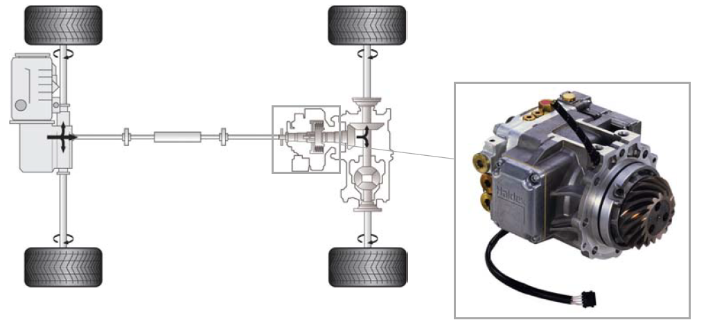
Haldex clutch model year 2004
When moving from the first generation to the second, the Haldex coupling principle did not change, but its design was improved. At the same time, the location of electrical and hydraulic components was changed.
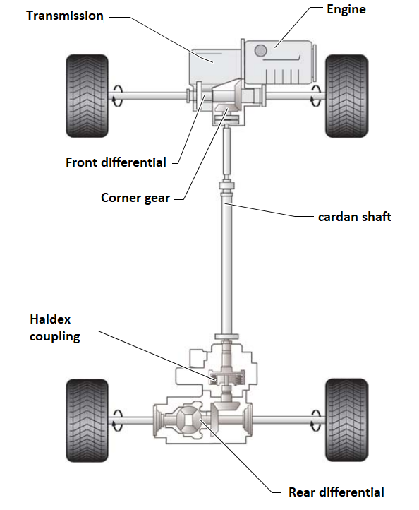
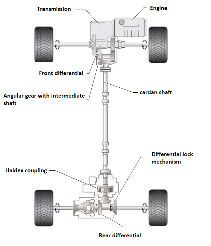
General design
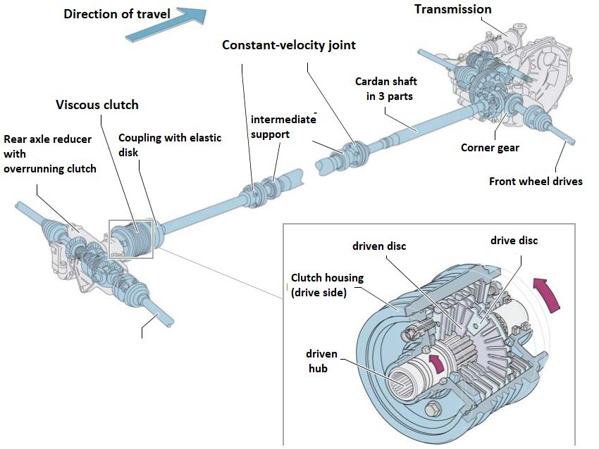
The front wheels are driven, as usual, through the front differential. Power is transmitted to the rear wheels via a bevel gear connected to the front differential box, a cardan shaft and a Haldex coupling mounted on the rear axle gearbox.
All-wheel drive 4MOTION Golf model 2004
All-wheel drive 4MOTION Transporter model 2004
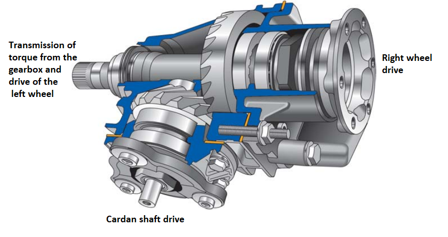
Angular transmission of the Golf model of 2004
The angular transmission of the Golf model 2004 provides a drive shaft with an increase in the frequency of rotation by 1.6 times. Since the transmitted torque is correspondingly reduced, you can use a cardan shaft with a smaller diameter. In the gearbox of the rear axle, the rotation frequency is again reduced by the above number of times.
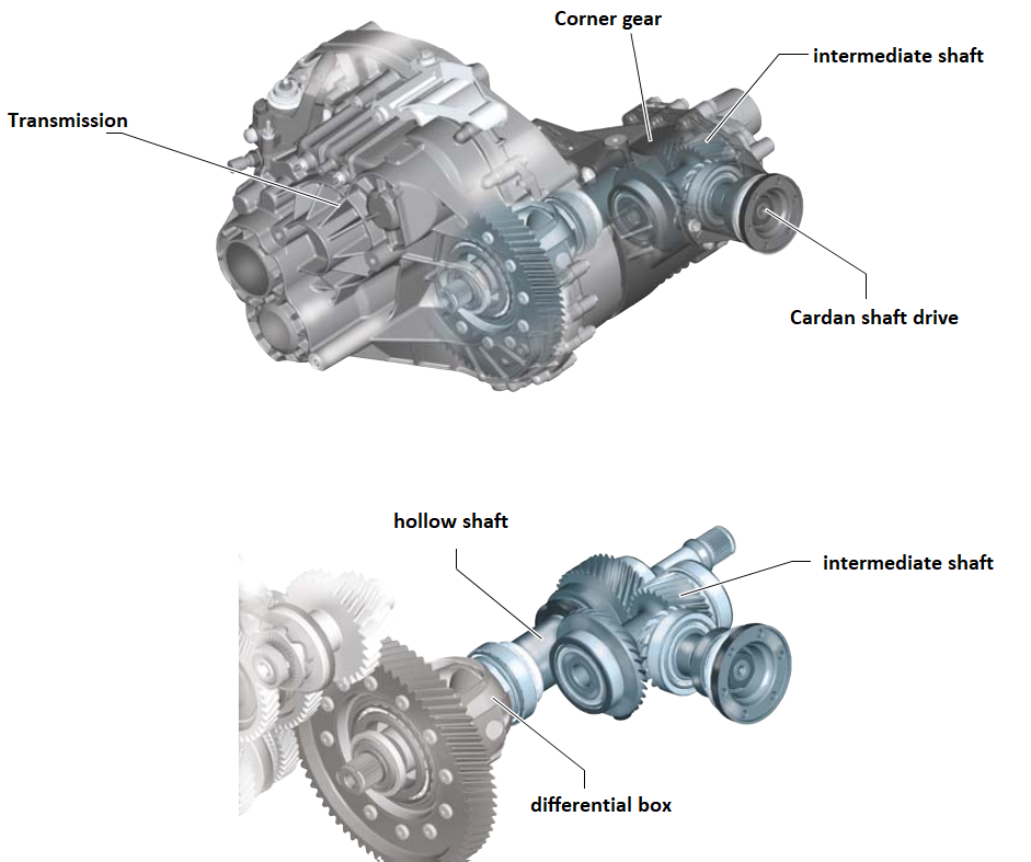
Angular gear with an intermediate shaft of a 2004 model Transporter car
Due to the large values of the torque transmitted through the transmission of the Transporter car, the rotation frequency of the cardan shaft is increased by 2.5. For this, the angular gear is supplemented with an intermediate gear. In the reducer of the rear axle, the frequency of rotation of its value on the front wheels is reduced.
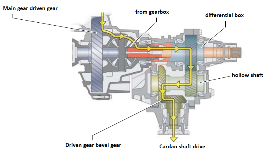
Transmission of power through the transmission of a 2004 Golf model
The power is transmitted to the cardan shaft from the driven gear of the main gear through the differential box, the hollow shaft and the driven gear of the bevel gear.
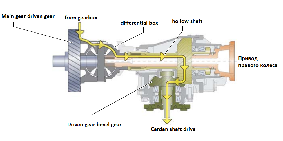
Transmission of power through the transmission of a 2004 model Transporter
From the driven gear of the main gear, the power is transmitted to the hollow shaft through the differential box. The hollow shaft is rigidly connected to the differential box. Power is transmitted to the cardan shaft through the intermediate shaft and the driven bevel gear.
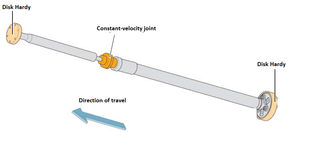
Cardan shaft. Golf car model 2004
The cardan shaft of the 2004 Golf model is equipped with two (elastic) Hardy disks and one joint of equal angular velocities.
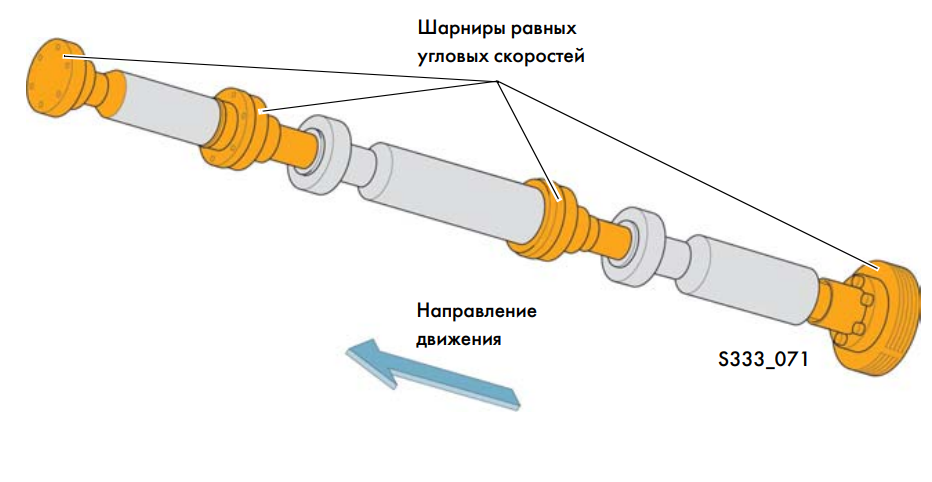
Transporter car model 2004
The cardan shaft of the Transporter model 2004 consists of three parts, between which and at its ends, joints of equal angular velocities are installed. Due to the large overall length of the shaft, an intermediate support fixed to the body is provided. Therefore, relatively large bending angles of the cardan shaft are obtained. To ensure the uniformity of the transmitted torque, it was necessary to use joints of equal angular velocities.
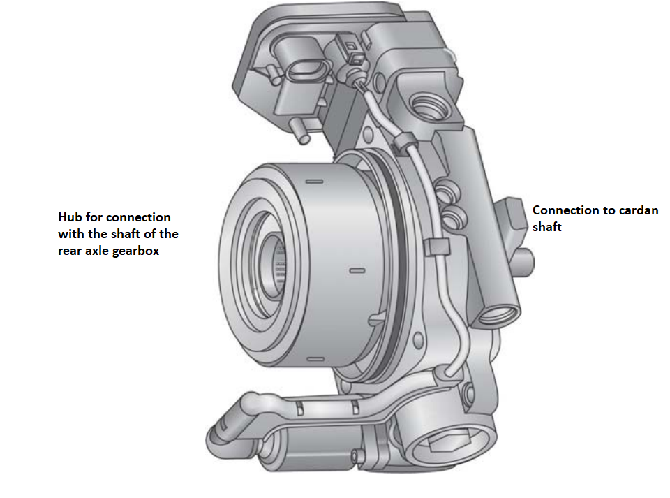
Haldex coupling
A Haldex coupling connects the driveshaft to the rear axle gearbox. It begins to act already at a rotation frequency of the engine shaft of 400 rpm. The clutch control unit regulates the torque transmitted by it in such a way that when the car is moving in a straight line, it works almost without slipping. This is achieved due to the appropriate compression of the disk clutch packages. Golf and Transporter models of 2004 use clutches of identical design. They differ only in the number of disks and elements of connection with the cardan shaft.
New elements in the 2004 model year Haldex clutch
The following changes were made to the design of the Haldex clutch of the 2004 model year:
- The Haldex clutch can be removed and replaced separately from the drive gear of the rear axle, which remains in its housing. In this case, there is no need to adjust the gearbox after replacing the clutch.
- Instead of a two-position electromagnetic valve for controlling the working pressure, a clutch control pressure regulator with a proportionally acting spool valve is used.
- Pressure and oil temperature sensors are combined in one housing.
- The paper filter has been replaced by a filter with an element made of non-woven material.
- The new Haldex clutch is organically integrated into the rear axle gearbox.
- The amount of oil poured into the clutch has been increased, and its change intervals have been extended accordingly.
Details and assemblies of Haldex clutches of the 2004 model year
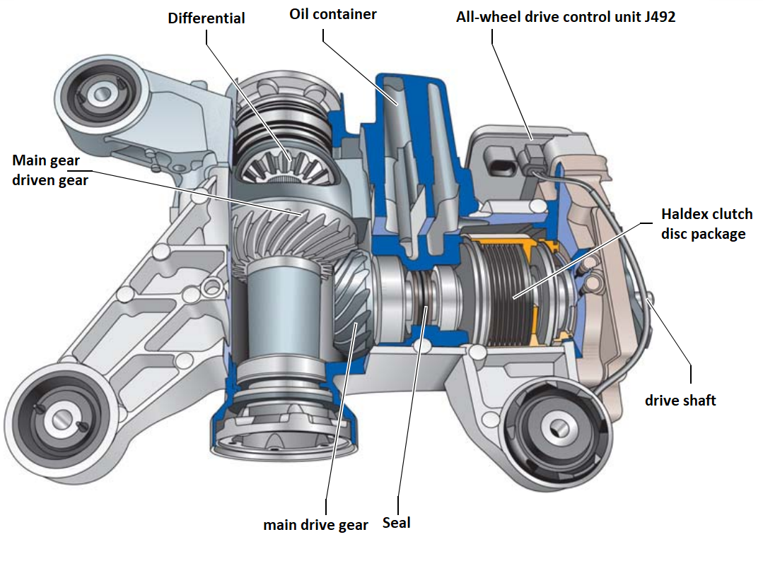
Rear axle reducer. Golf car model 2004
The 2004 Golf 4MOTION does not have a rear differential lock mechanism. The gear ratio increases the angular transmission equal to 1.6.
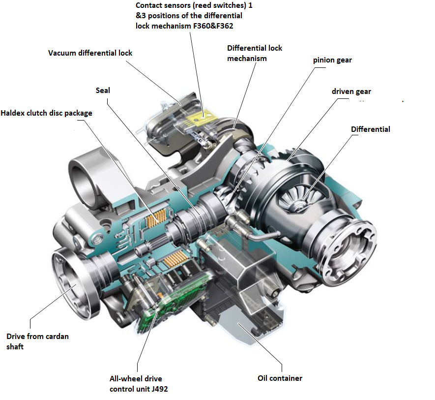
Transporter car model 2004
The 2004 Transporter 4MOTION all-wheel drive system includes a Haldex clutch, a rear axle gearbox and a custom-fit differential lock mechanism. The gear ratio of the rear axle gearbox is 2.5.
The designs of the rear axle drives of Golf and Transporter models 2004 differ in the following:
- the Golf car does not have a differential lock,
- the transmission ratios of the drives are different,
- oil containers are structurally different,
- various elements of connection with the rear axle reducer,
- the number of discs in the clutch.
Haldex clutch device
The 4MOTION all-wheel drive of the 2004 Golf and Transporter models is equipped with a Haldex clutch of the second generation. Below is a schematic drawing explaining its device.
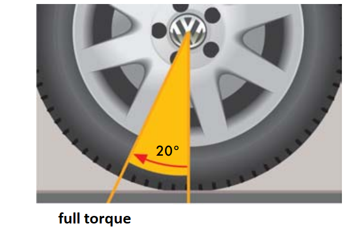
Conditions for turning on the Haldex clutch of the 2004 model year
The Haldex clutch plate package begins to transmit torque when the front and rear wheel angles differ by just 10°, and with a difference of 20°, full torque can be transmitted.
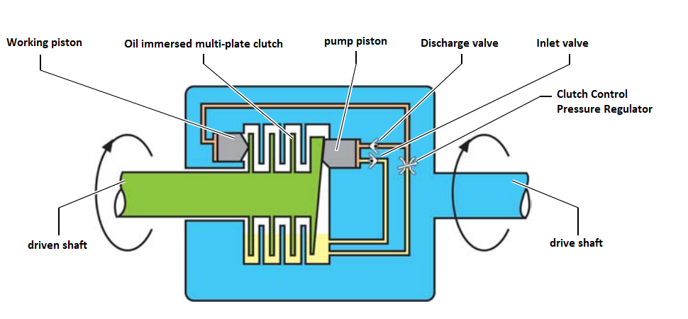
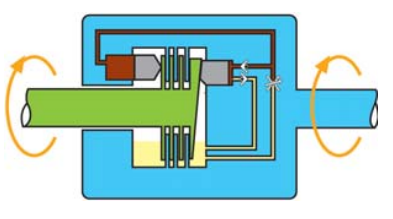
The principle of the Haldex coupling
When the rotation frequencies of the front and rear wheels differ, the drive shaft of the clutch rotates together with the roller of the pump piston relative to the cam washer connected to the driven shaft. At the same time, the driven shaft rotates more slowly than the driving shaft.
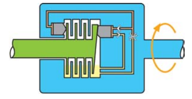
The variable translational movements of the pusher roller are transmitted to the pumping (conducting) piston, the movement of which is used to supply oil, which is used as a working fluid.
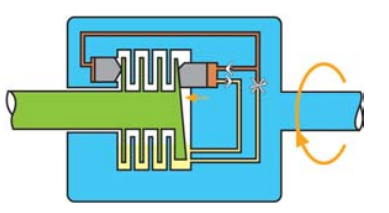
The oil is pumped into a channel through which it is fed to the working (known) piston. Under the influence of oil pressure, the working piston moves to the right, compressing the disk pack.
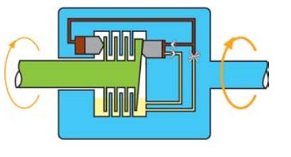
As a result of the compression of the disk pack, the drive shaft of the clutch is connected to the driven shaft. In this way, the drive is carried out on all wheels of the car with the transmission of the turning moment to the rear wheels.
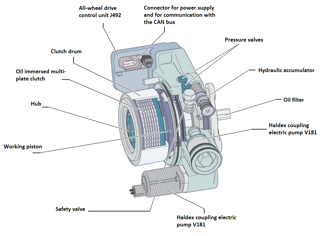
2004 model year Haldex clutch parts and assemblies
Haldex clutch components form three systems, namely:
- mechanical,
- hydraulic and
- electronic (electric).
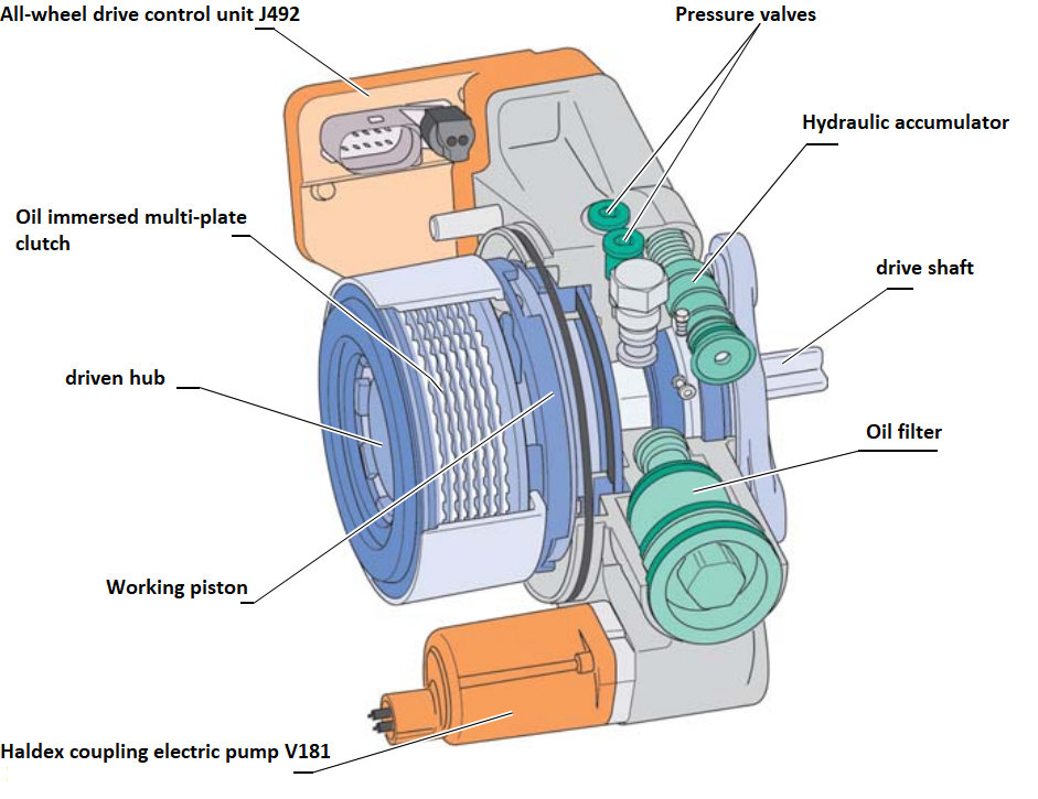
The mechanical part of the clutch
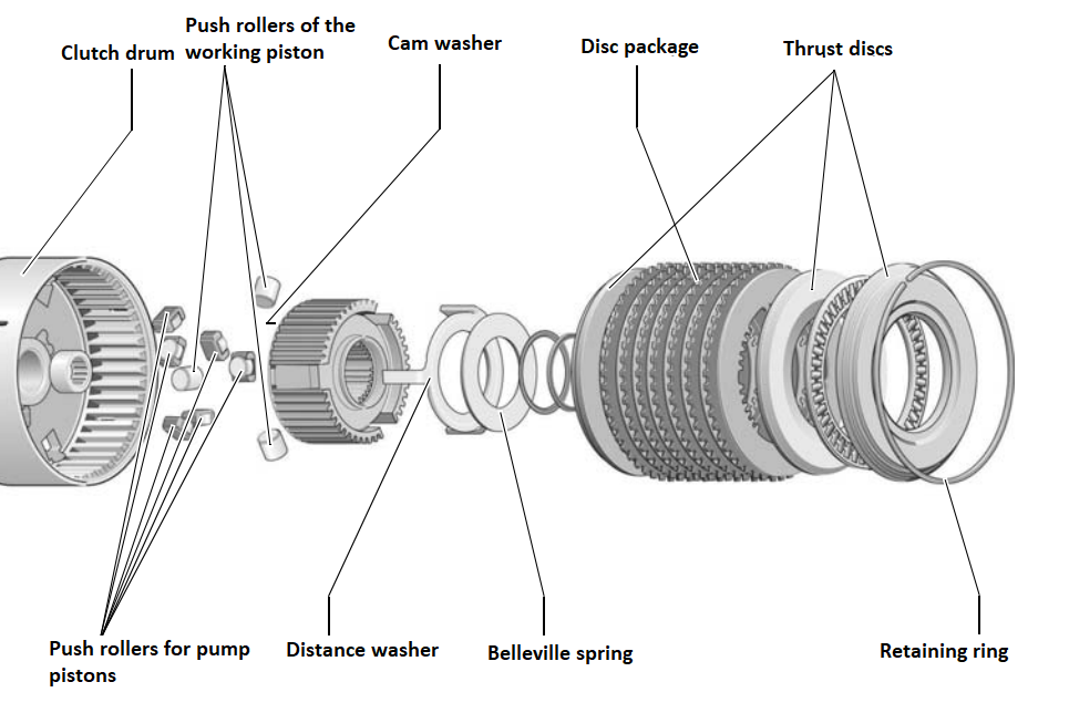
The main parts of the Haldex clutch include a drive shaft with a drum, drive discs that engage with it, drive hubs with a cam washer, and driven discs that engage with it. The main parts also include the working piston. On the next double page is a drawing showing almost all the details of the clutch mechanism.
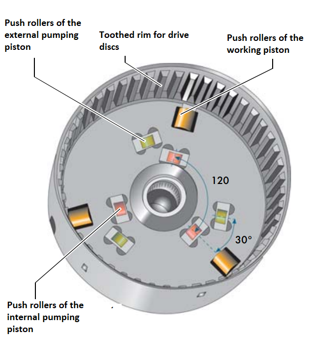
Pump pistons supplying oil to the system are driven by rollers. There are external and internal pistons, each of which rests on three rollers located in a circle at 120 ° intervals. Pump pistons make three full strokes for one revolution of the cam washer. The rollers of the outer and inner pistons are offset by 30°, due to which the phase of oil supply under pressure is extended. This measure contributes to the reduction of the clutch actuation delay. The pack of discs compressing the working piston also rests on three rollers spaced 120° apart.
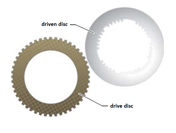
The external teeth of the driving disks, located on the perimeter, are engaged with the toothed crown of the clutch drum. Driven disks are equipped with internal teeth that mesh with the external teeth of the hub. All discs are made of steel.
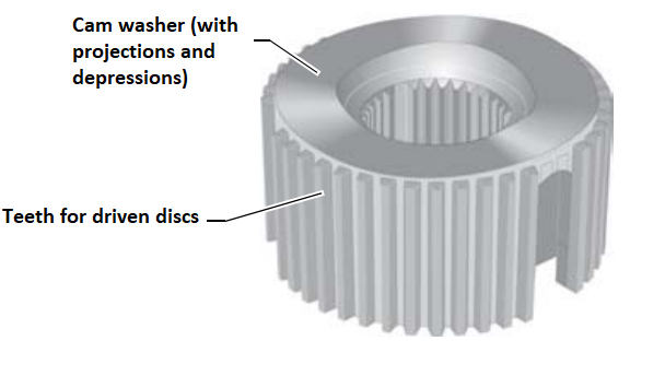
The cam washer has protrusions and depressions that cause the movement of the pump pistons that supply oil to the system.
General appearance

The working piston and both pump pistons have an annular (toroidal) shape. With a difference in the rotation frequency at the input and output of the clutch, the protrusions of the cam washer run into the rollers of the pump pistons, forcing them to move back and forth. At the same time, the pump pistons supply oil under pressure, which is transmitted to the working piston. The force created by the working piston is transmitted through the rollers to the hard disc of the multi-disc package, compressing the latter.
In order to minimize the frictional forces acting between the discs when the clutch is off, the latter are additionally compressed by a disk spring. The spring expands the discs until there is no oil pressure created by the pump pistons.
Details of the hydraulic system
The hydraulic system includes valves and a hydraulic accumulator. In total, the clutch design has 5 valves that open or close under the action of springs. It:
- two intake valves,
- two discharge valves,
- one safety valve.
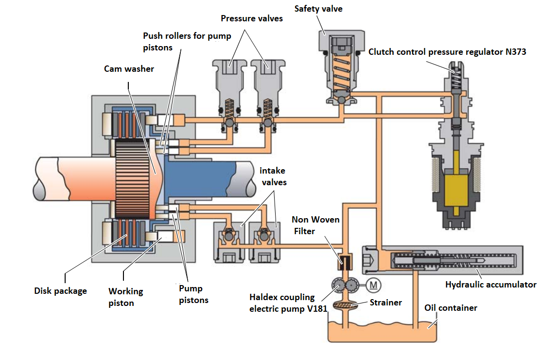
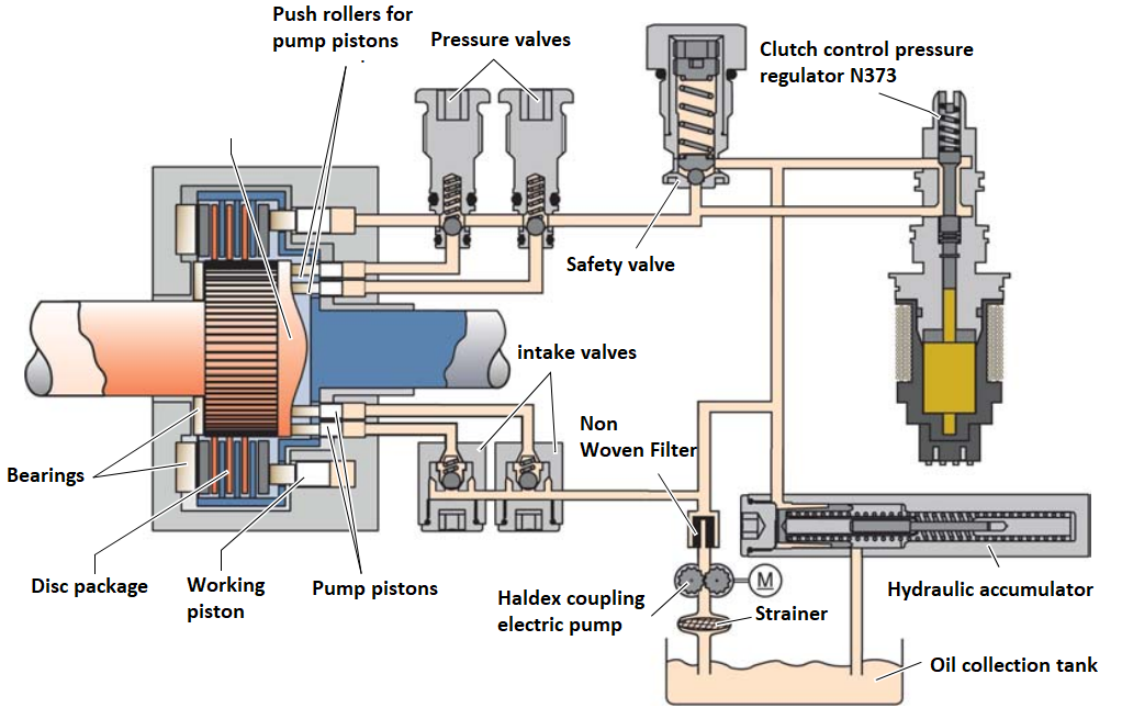
Hydraulic circuit
All components of the hydraulic system are shown in the figure below. For ease of understanding, the drawing is simplified: instead of three pairs of pump piston rollers, only two pairs of rollers driven by the cam washer are shown. In fact, three pairs of these rollers are located in a circle through 120 °.
Hydraulic accumulator
The hydraulic accumulator equipped with a spring serves to stabilize the oil pressure in the supply line. In the 2004 Golf, this pressure is maintained at 3.2 bar, and in the 2004 Transporter - at 3.8 bar.
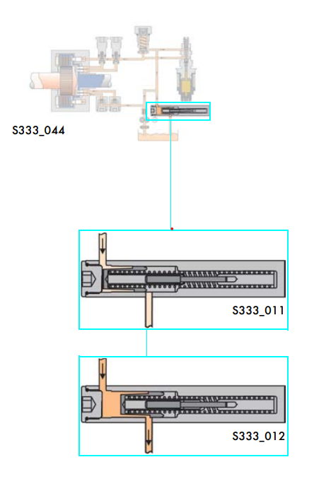
In the absence of pressure in the supply line, the battery spring is maximally compressed and oil does not drain through the battery from the supply line. The increase in the pressure of the supply line is limited to a given level due to the bypass of oil from it through the accumulator into a container for its collection. When the pressure drops, the battery spring is stretched, reducing or completely stopping the discharge of oil into the tank.
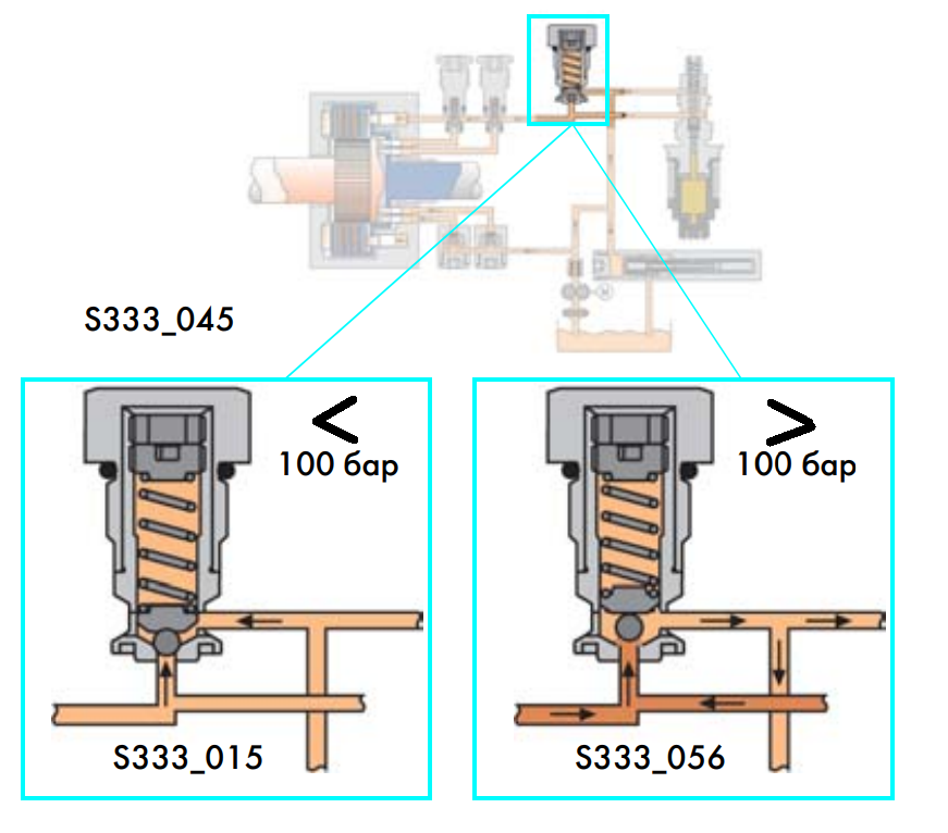
Safety valve
The safety valve prevents the control pressure from rising above 100 bar, protecting the coupling parts from overloads. The valve opens if the pressure on its closing body overcomes the force of the pre-compressed spring. When the pressure increases to 100 bar, the valve opens, passing oil into the supply line and into the tank through the hydraulic accumulator. As a result, the oil pressure in the system decreases to the specified level.
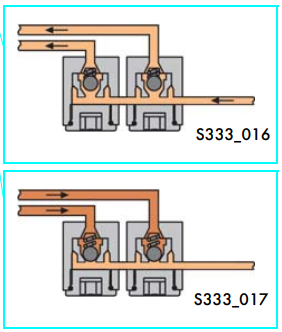
Inlet valves
Inlet valves close the supply line, connecting it to the pump cylinders. The valves are equipped with springs that allow them to open during suction. During injection, the intake valves are closed, ensuring a rise in pressure in the pump cylinders and, accordingly, under the working piston.
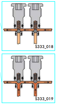
Discharge valves are located in the pipeline between the pump cylinders and the working cylinder. A circuit with a safety valve and clutch control pressure regulator N373 is connected to this line. The springs of the discharge valves are adjusted in such a way that the valves open when the pressure below them exceeds the pressure of the supply line. After opening the valves, the pressure created by the pump pistons is transferred to the working piston. At the same time, the pump cavities are communicated with the clutch control pressure regulator N373. The degree of closing of the clutch depends on the value of this pressure. During the return stroke of the pump piston (on the run of the cam acting on it), the discharge valve corresponding to it is closed, preventing a drop in the pressure transmitted to the working piston.
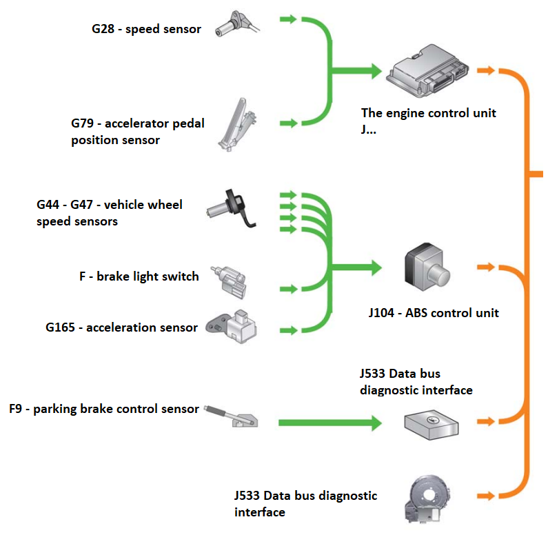
Clutch control system. Sensors
Clutch control system. Executive devices
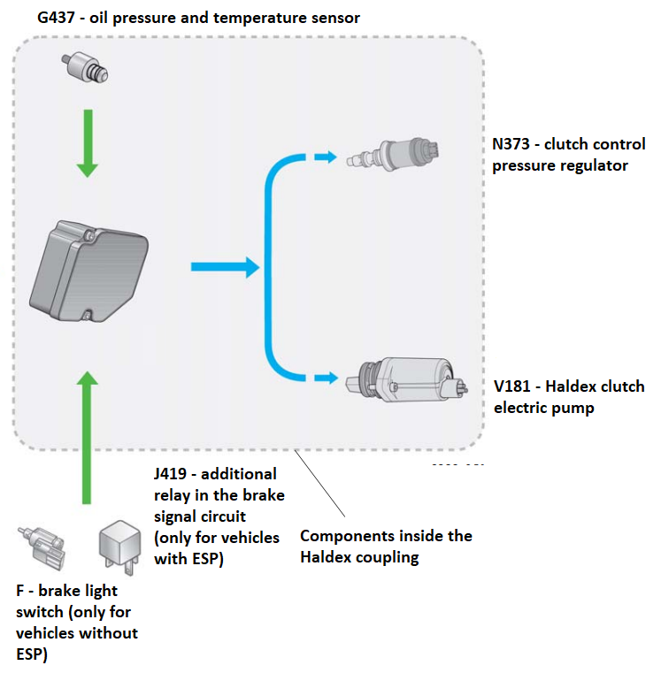
Electrical and electronic components
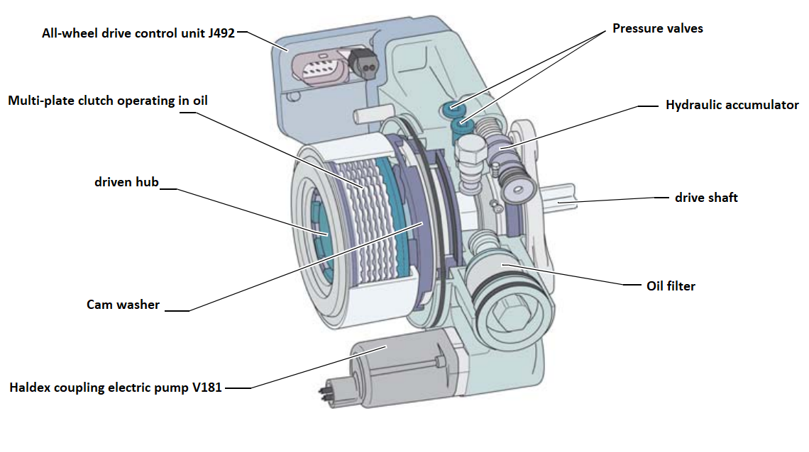
Clutch electrical and electronic components include oil pressure and temperature sensor G437, electric pump V181 and clutch control pressure regulator N373. In addition to them, the Haldex clutch is under the control of its own control unit, known as the four-wheel drive control unit J492.
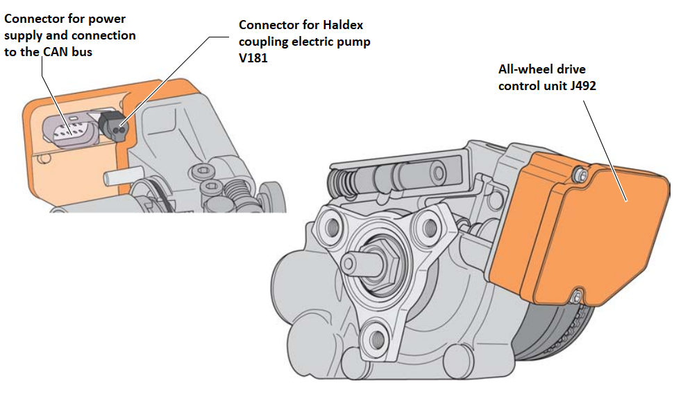
All-wheel drive control unit (J492)
When switching to the second-generation Haldex clutch, the J492 four-wheel drive control unit was connected to the CAN powertrain buses. Thanks to this, it was possible to increase the efficiency of the clutch adjustment when using a small number of own sensors (in particular, the oil pressure and temperature sensor). The control unit receives information from the oil pressure and temperature sensor G437 and data about the vehicle's driving mode via the CAN bus, analyzes them and sets the degree of correspondence between the working pressure, the degree of clutch engagement and the transmitted torque. When the ESP or ABS system is active, the four-wheel drive control unit J492 ensures the opening of the Haldex clutch.
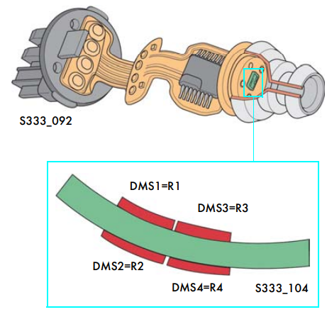
Sensors located in the housing of the Haldex coupling
In one common body of the sensor, there are sensitive elements that respond to changes in oil pressure and temperature. Temperature measurement is carried out in the form of a sensitive element with a negative temperature coefficient. The pressure is measured using a sensitive element with strain gauges (DMS) connected according to the bridge circuit. A change in pressure leads to a change in the ohmic resistance (R) of strain gauges. In the range up to 100 bar, the working pressure is changed by the regulator N373 in accordance with the vehicle's driving modes. Oil pressure and temperature measurement data are used when selecting clutch engagement modes.
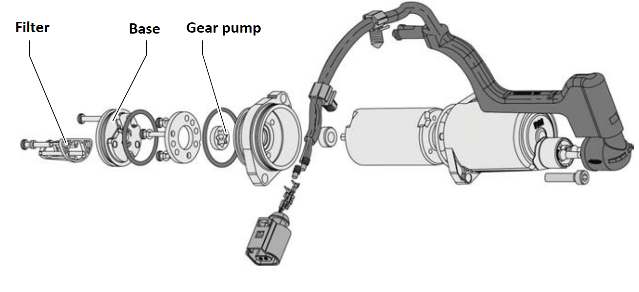
Haldex clutch electric pump (V181)
The electric pump V181 constantly pumps oil into the feed line, maintaining the pressure in it, which is necessary for quick closing of the clutch. This pump works constantly during the operation of the car, ensuring reliable filling of the hydraulic system with oil.
Clutch Control Pressure Regulator (N373)
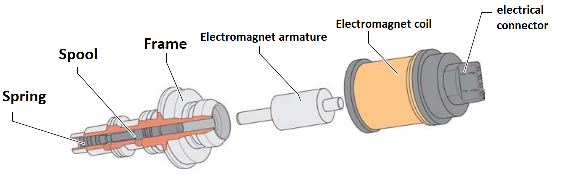
Clutch control
The processes taking place in the clutch hydraulic system under different vehicle driving modes are discussed below. First, the processes that occur when the ignition is turned on and when the engine is brought to full load are described.
Processes in the control system when the ignition is turned on
If the ignition is on, but the engine shaft rotation signal is not received, there is no pressure in the hydraulic control system. The springs of all valves are relaxed. The pressure in the system is not created, the oil is not pumped.
Processes in the control system at full engine load
At full engine load, the N373 pressure regulator spool completely blocks the oil flow. At the same time, the working pressure is not regulated. The full pressure created by the pump pistons acts on the working piston. Inlet valves block the passage of oil from the pump cylinders in the direction of the electric pump and hydraulic accumulator. Discharge valves open when oil is supplied by the pump pistons in the direction of the working piston and close when the pump pistons move away from the cams that coincide. This creates a power connection between the clutch drive shaft and the driven shaft. The maximum working pressure depends on the tightening of the safety valve spring. This valve opens at a pressure of 100 bar, allowing the oil to drain through the hydraulic accumulator
In this case, the typical driving modes are intensive acceleration or driving on ice with the front wheels. At the same time, the difference in the frequency of rotation of the front and rear wheels increases sharply and there is a need to transfer a large torque to the rear wheels.
Processes in the control system when the engine is idling
Bringing the hydraulic system to working condition:
● Turning on the ignition, the crankshaft speed exceeds 400 rpm.
● The four-wheel drive control unit J492 recognizes the situation and issues a command to turn on the electronic pump of the Haldex V181 clutch. The pump kicks in and raises the supply pressure to the set level (3.2 bar for a 2004 Golf and 3.8 bar for a 2004 Transporter).
● Since there is no difference in the frequency of rotation of the front and rear wheels, the pump pistons do not work.
● The inlet valves are opened by the supply pressure applied to the pump cylinders.
● Supply pressure is also distributed through open clutch control pressure regulator N373 to the operating piston.
● The clutch discs are lifted by the force created by the working piston.
● As a result, the hydraulic system is quickly and completely filled with oil and thus brought into working condition.
Processes in the control system at partial engine loads
The state of the hydraulic system in working modes
● In the hydraulic system, the oil is under a certain supply pressure.
● Under certain driving conditions, there is a difference in the frequency of rotation of the front and rear wheels.
● Pump pistons move and pump oil under pressure into the control line.
● The inlet valves are closed during oil supply.
● Discharge valves open, allowing oil under pressure to the operating piston.
● The working piston transmits pressure through the rollers and the idler disk to the clutch pack, compressing them.
● The clutch control pressure regulator N373 closes the control line or drains part of the oil from it according to the commands issued by the four-wheel drive control unit J492.
● Thus, the clutch is fully or partially closed depending on the driving conditions of the vehicle. At the same time, the torque is transmitted to the rear wheels as neededи.
Also read about Haldex generation V all-wheel drive clutch.