What is FlexRay?

AvtoAd
16/11/2022
Content
2. Electrical implementation of FlexRay.
3. The principle of transmission on the FlexRay bus.
9. Synchronization on the FlexRay bus.
10. Disadvantages of the FlexRay tire.
What is FlexRay?
FlexRay is a high-speed data transmission bus for cars. It is used in particularly responsible areas of data exchange, for example, in steer-by-wire or brake-by-wire systems. Such systems assume the absence of a direct mechanical connection between the control body and the executive device. Therefore, it is very important to use a highly reliable communication channel.
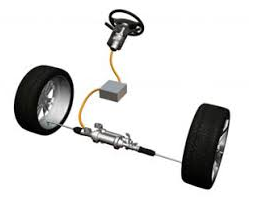
The speed of the FlexRay bus can reach 10 Mbit, which allows it to be used not only in areas that require high reliability of data transmission, but also high speed. For example, FlexRay can be used as a core bus in a multi-domain network architecture.
Electrical implementation of FlexRay

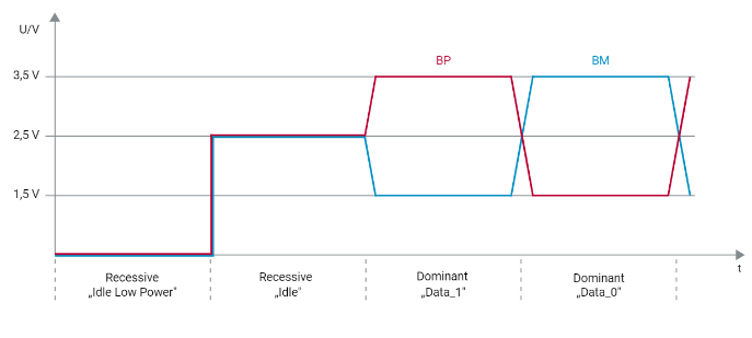
At the level of equipment and electrical signals, the FlexRay bus is implemented similarly to the CAN bus - it is a current loop with signal transmission via an unshielded twisted pair.
Just like the CAN bus, the recessive and dominant states of the bus are used to encode bits.
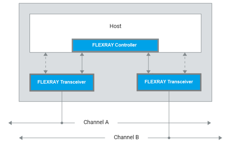
For higher reliability, each controller connected to the FlexRay network can use two physical data transmission channels. But mostly one is used.
The principle of transmission on the FlexRay bus
The key feature of the FlexRay bus is the use of the TDMA principle.
TDMA or Time Division Multiple Access is a method of multiplexing transmission from different sources with time division access to the transmission channel.
Or a literal translation - multi-channel access with time-division channels.
The principle of TDMA determines that all nodes included in the channel can transmit data exclusively in the time interval allocated specifically for them. At other times, these nodes cannot send messages. The TDMA mechanism allows you to eliminate collisions in the channel, as well as protect the bus from unauthorized messages. Therefore, it will not be possible to use programs such as CAN Bomber on the FlexRay bus, because all frames outside the allowed ones will be ignored.
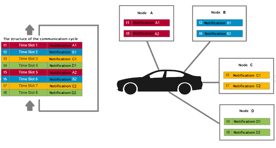
A communication cycle on a FlexRay bus consists of several segments, and the segments are divided into time slots.
There are segments:
- Static segment . Static segment - guarantees real-time operation and exclusion of collisions. In this entire segment, the TDMA principle works. Each node is obliged to transmit the message to its temporary slot.
- Dynamic segment . Dynamic segment - data transfer is used with binding to any event. In this time slot, FlexRay is conceptually similar to a CAN bus - it can transmit to any node, but also within the time slot schedule set on the bus. (FTDMA – flexible multiple access with temporal division of channels).
- Symbol Window – serves to transmit FlexRay service messages, for example, to wake up the bus.
Segments can be combined in one communication cycle as follows:
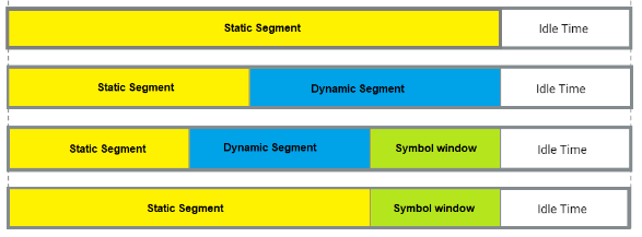
Dynamic segment and Symbol Window are not mandatory in the communication cycle. The main segment is a Static segment , as its operation is governed by the TDMA principle.
Static segment
Static segment is divided into temporary slots. According to the TDMA principle, in each specific time slot of a static segment (Static Segment), only a specific node accesses the bus, the rest are silent.
Dynamic segment
A dynamic segment is an optional segment that, if present, always follows a static segment. The principle of time division also applies in the dynamic segment, but it is more flexible than in the static segment.
In each time slot of a dynamic segment, a node may or may not transmit a message, depending on whether an event has occurred that causes the message to be sent.
FlexRay frame structure
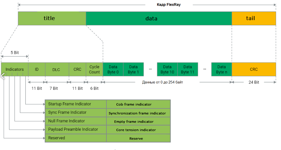
Each frame (frame, message) on the Flex Ray bus consists of a header, a payload (Payload, data fields) and a tail (Trailer).
FlexRay header structure
The message header consists of 40 bits and contains the following elements:
- Indicator bits - serve to determine the type of message
- Message identifier ID – 11 bits
- DLC is a field indicating the length of the payload in 16-bit words (One 16-bit word is two bytes).
- CRC is a checksum. Calculated based on ID, DLC, StartUp Frame Indicator, Sync Frame Indicator and FlexRay polynomial generator values.
- Cycle counter – counter of communication cycles. Considers messages from 0 to 63.
PayLoad payload
The length of the payload can be up to 254 bytes and is determined by the packet header.
For Static Segment, the payload length is always constant and is determined at the network design stage.
The first 12 bytes of the payload transmitted in the static segment can be used to transmit the FllexRay network control vector. For this, the Payload Preable Indicator bit must be set in the frame header.
For a Dynamic Segment, the length of the payload can be different. If the Payload Preamble Indicator bit is set when transmitting a message in a dynamic segment, it means that the first two bytes of the payload are used as a network control vector or an additional message identifier.
In special cases, the sender may send a message payload with zeros only. This case exists if the FlexRay controller needs to send a static message according to the communication schedule, but the buffer corresponding to the message is blocked by the host. This can happen, for example, if the host itself accesses this buffer now. Since the FlexRay controller cannot access the data in the buffer, it automatically transmits a static message as a null frame. In this case, the zero frame indicator becomes zero in the message header.
The CRC method (CRC: Cyclic Redundancy Check) is used to protect the payload. The CRC is calculated based on the header, payload, and generator polynomial defined in the FlexRay specification. This CRC sequence is added to the header and payload as a trailer (Tail).
Synchronization on the FlexRay bus
On the FlexRay bus, it is necessary to ensure that - from the point of view of all FlexRay nodes - all communication cycles always start at the same point and have the same length. It is also necessary to ensure that all static FlexRay node slots always start at the same point in the cycle. Therefore, it is very important to clearly synchronize all nodes of the network.
The synchronization of nodes in the FlexRay network is based on the fact that the time points of sending and receiving all static messages are known to each FlexRay node from the very beginning. This ensures that all nodes in the FlexRay cluster can adjust for both elimination and speed. After just a few cycles, all FlexRay nodes start each communication cycle at the same moment in time and at the same speed.
In a FlexRay cluster, 2 to 15 FlexRay nodes act as synchronization nodes (sync node) that transmit synchronization messages (SYNC Frames) in a specific static slot each cycle. These are not additional messages, astatic messages in which the Sync Frame Indicator is set.
Nodes on the bus compare the actual arrival time of synchronization messages and the time specified in the schedule and, based on the difference, adjust the course of the node's local clock.
Disadvantages of the FlexRay tire
FlexRay has a number of serious disadvantages that limit the use of this technology:
- High node cost. Controllers capable of working with high temporal accuracy and special transceivers are required.
- Low signal level limiting the maximum length of the bus.
- The consortium of developers of the FlexRay bus broke up and the further development of the technology has not been determined.