What is a LIN bus
AvtoAd
04/09/2023
The main characteristics of the LIN bus
Example of a door control system with and without a LIN bus
Electrical implementation of LIN
Connecting the LIN transceiver to the microcontroller
LIN tire
LIN (Local Interconnect Network) bus is a communication system in cars, designed to control less demanding devices in terms of speed and reliability, such as windows, mirrors, seats and other comfort devices. The LIN bus is an alternative to the more complex and expensive CAN bus used for critical systems such as brakes, engine control, etc.
The main characteristics of the LIN bus
- Architecture: Centralized system with one master and several slaves.
- Physical level: Single-wire circuit with the possibility of connecting up to 15 nodes.
- Voltage: Typically 12V, as in most automotive systems.
- Protocol: Simplified compared to CAN, with a built-in mechanism for error detection and correction.
- Applications: Simple automotive electronics systems such as lighting, mirrors, windows, seats, etc. controls.
An example of a door control system with and without a LIN bus:
Without LIN :

With LIN bus :

Another example, which is used in BMW cars, VAG car group, Mercedes and other modern cars, when all damper servos and digital sensors of the climate system are connected using the LIN bus, and the climate control unit itself is connected to the car using the CAN bus.
The cheapness of LIN is due to the fact that the implementation of the LIN protocol is completely software and is built on the basis of a regular UART (relative of RS232, COM port). Also, LIN does not require the use of precise timing circuits - quartz resonators and generators. Therefore, you can use cheap microcontrollers.
Data transfer speed
The data transfer rate on the LIN bus is standard for devices built on the basis of UART, usually up to 20 kbps.
It's not much, but it's enough to transmit data from sensors and control slow mechanisms.
Electrical implementation of LIN
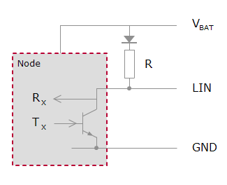
Electrically, the LIN interface is implemented just as easily. In each node, the bus line is pulled to the +12V bus. Transmission is carried out by lowering the GND ground level bus level. The microcontroller is connected to the LIN bus using a special Transceiver chip, for example TJA1020 (TJA1021)
Electric circuit of the LIN bus
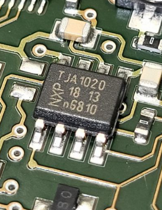
Appearance of the TJA1020 chip from NXP
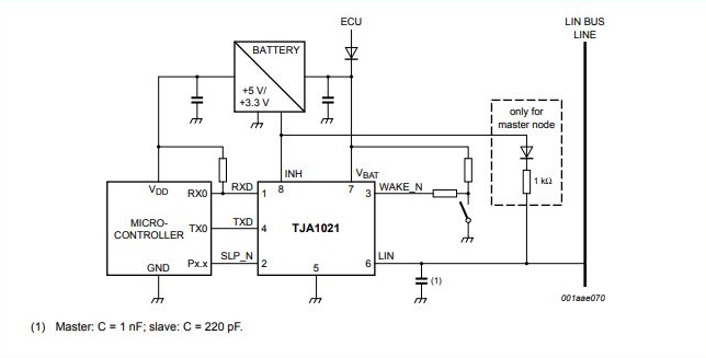
Connecting the LIN transceiver to the microcontroller
LIN network architecture
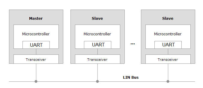
The peculiarity of the LIN bus is that there are two types of nodes in the network: Master and Slave.
Master – leading,
Slave is subordinate.
The Master can poll the Slave about its status, wake it up, send commands to it. Information exchange on the LIN bus takes place in the format of packet exchange, and at first glance it may seem that the mechanism is identical to the CAN bus, it is not so. We explain why:
The structure of the LIN packet looks like this:
Frame LIN
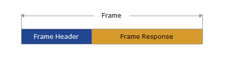
Frame – Header – frame header sent to the bus by the Master. Includes frame ID
Frame – Response – data sent by the Slave in response to the Master's request.
Catch the Difference – in the CAN bus, all nodes transmit both frame ID and data. In the LIN bus, the packet header is the task of the Master node.
LIN frame structure

The Frame-Header field consists of the following fields:
BREAK – This is a bus signal that the master will now speak
The sync field is simply byte = 0x55 . When transmitting it, the receivers adjust their speed.
PID is a secure identifier field. In the future, we will simply write - identifier.
The identifier can take values from 0 to 59 (0x3B in HEX) for user packets. It is also possible to use special service packages with IDs 0x3C, 0x3D, 0x3E and 0x3F. The security of the identifier is as follows:
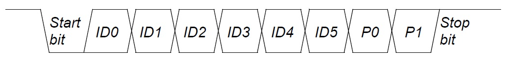
In the structure of the ID byte, we see the bits of the identifier itself from ID0 to ID5, and then there are two control bits P0 and P1, which are calculated as follows:
P0 = ID0 ⊕ ID1 ⊕ ID2 ⊕ ID4
P1 = ¬ (ID1 ⊕ ID3 ⊕ ID4 ⊕ ID5)
Example:
ID = 0x00 PID = 0x80
ID = 0x0C PID = 0x4C
If the control bits in the PID are calculated incorrectly, the packet will not be processed by the receiving party.
If we emulate the operation of some Master node, having previously studied the data sent by it using the sniffer's LIN, then we do not have to think about the calculation of the ID control bits, since everything is already calculated for us in the packets that we see by the sniffer.
After the Slave has received the Master's Header, it responds with the Frame Response field, which consists of data bytes in the number from 1 to 8 and a checksum byte.
Checksum (CRC) is considered as the inverted sum of all data bytes with the carry or the sum of all data bytes + the value of the protected ID . In the first case, CRC is called classic, in the second case, it is called extended. The version of the checksum calculation is determined by the version of the LIN-bus standard. In versions 1. XX, the classic algorithm is used, in versions 2. XX, an advanced algorithm is used.
Note the absence of the DLC field, which is responsible for the number of data bytes as in the CAN bus. In the LIN bus, the number of data bytes is determined at the stage of writing the controller software. Therefore, the process of exchange on the LIN bus is more difficult to analyze with the help of a sniffer - it is necessary to introduce a special packet splitting algorithm that guesses how many bytes of data were in the received packet.
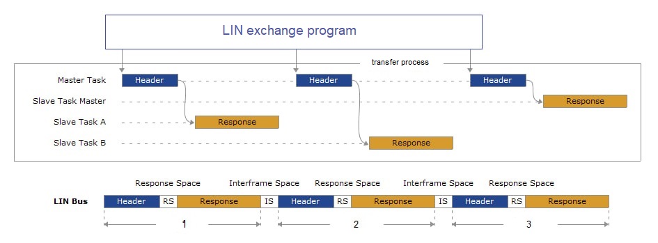
In this diagram, we see how one Master communicates with two Slave nodes. Pay attention to the third frame, in it the Header header and the body of the Response packet are transmitted by the Master - this is an important point, such frames are used to diagnose and configure the Slave nodes.
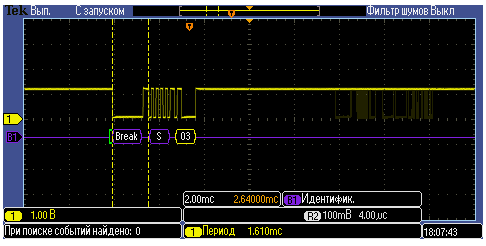
On the oscillogram, the exchange of one Master and one Slave looks like this:
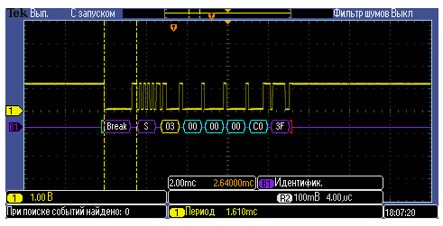
Here we see the request of the master consisting of the fields Break - S - ID = 0x03, followed by the response of the Slave node consisting of four bytes and a checksum equal to 0x3F.
If we disconnect the Slave node from the LIN bus, we will see the following oscillogram:
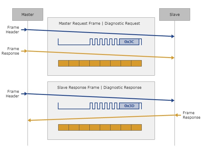
Also, the LIN bus protocol provides special service packages for bus diagnostics, device wake-up, and other functions. In this case, the Master can transmit both Frame Header and Frame Response sequentially, then the Master packet can look like this:
ID = 0x3C DATA : FF FF FF FF FF FF FF FF
The exchange of diagnostic messages on the LIN bus looks like this:
With the help of long packets, the Master can configure and program the Slave nodes. If programming or configuration of the LIN node requires more than 8 bytes, the data stream is segmented and forwarded in parts. The mechanics of data transmission are determined by a special transport protocol that works on top of the physics of the LIN bus, which we will write about in future articles.
The lion's share of the material is from this site .