UDS protocol (Unified Diagnostic Services)

AvtoAd
10/11/2022
The UDS protocol is the “language” used by diagnostic equipment to communicate. The UDS protocol can work on different physical buses: K-Line, CAN, FlexRay. In this article, we will consider the mechanism of operation of the UDS protocol on the CAN bus as the most common option at the moment. We will consider the issue from a practical point of view for the speed of material perception. The protocol is described in detail in the ISO-15765 standard .
Using the UDS protocol, it is possible not only to count\erase error codes - DTCs, but also to request the current parameters of sensors and control units (ECUs), as well as to give commands to actuators (for example, open\close the central locking).
In addition, this protocol is used to flash control units.
In the database, the UDS protocol is built on the TP transport protocol. Transport is not in the sense of its application in transport, but in the sense that the protocol is designed for transporting data over some transmission channel.
Content
1. Description of the TP transport protocol.
3. UDS frame.
4. Detailed analysis of specific examples of using the UDS protocol.
5. Detailed analysis of specific examples of using the UDS protocol.
6. Table of command failure codes.
Description of the TP transport protocol
The frame of the transport protocol is built according to the following scheme:
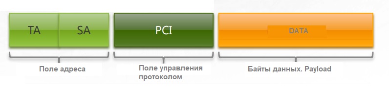
TA – Target Address or the address of the recipient of the frame
SA – Source address or the address of the sender of the frame
PCI – The field in which the number of transmitted bytes and the frame type are coded.
In the implementation of the UDS protocol operating on top of the CAN bus, the source address is not specified in the frame header, and the recipient address is the CAN ID of the entire frame.
For example, in the CAN message 0x7E0 02 09 02 00 00 00 00 00 00, the addressee will be the engine control unit whose address is =0x7E0.
Types of frames
Single Frame SF - Single frame. A frame, all the information of which is contained in one CAN packet.

Example: 0x7E0 02 09 02 00 00 00 00 00 .
PCI field in case = 0x02. It indicates that there will be one frame and its length is 2 bytes: 09 02
First Frame FF – The first frame of a series of frames
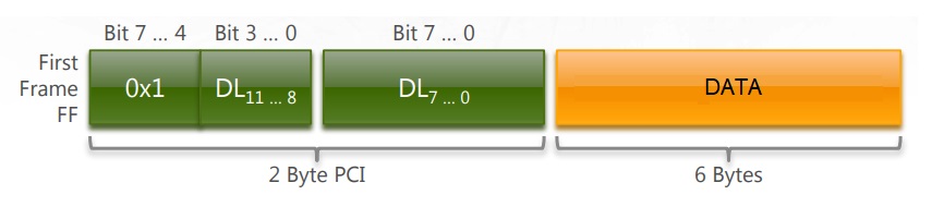
The PCI field occupies two bytes: Zero and first. The 7 bits of the first byte and the 3 first bits of the zero byte determine the length of the message - a maximum of 2048 bytes.
The fourth bit of the zero byte is equal to 1, indicating that this is the First Frame.
Example: 0x7E8 10 14 49 02 01 57 41 55
PCI = 1014. First frame. The length of the data field is 0×14 or 20 bytes.
DATA : 49 02 01 57 41 55 - six bytes
Thus, after this frame, 2 more frames with a load of 7 bytes of data each must be sent, so that a total of 20 bytes is obtained.
Consecutive Frame CF - the next frame. Each frame follows the First Frame from the same sender.
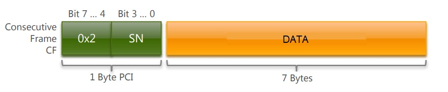
The PCI field occupies a zero byte. The upper half of the byte =0x2 and indicates that we have a CF frame. The lower half indicates the sequence number of the CF frame from 0x0 to 0xF.
Example: 0x7E8 21 5A 5A 5A 38 45 37 37
PCI = 0x21. Frame type – CF, frame number =1
Flow control Frame – FC – flow control frame. Sent by the recipient in response to a First Frame.

The FC frame is used for flow control if the First Frame-Consecutive Frames frame flow is used.
PCI takes three bytes: Zero, first, second.
The 0x3 header in the PCI field header indicates that this is an FC frame.
Flow Status tells the sender of the First Frame about the status of the receiver 00- Ready to receive CF frames, 01-Waiting, 02 - Overflow.
Block Size determines the number of SF frames that the receiver is ready to accept. Some may have zero and the protocol will still work.
Minimum Separation Time in milliseconds, sets the minimum time between CF frames being transmitted.
Example 1: 0x7E0 30 02 00 00 00 00 00 00
FC frame.
Willing to accept 2 CF frames.
With minimum time between CF frames = 0 milliseconds.
Example 2: 0x778 30 08 05 AA AA AA AA AA
FC frame
Ready to accept 8 CF frames
With a minimum delay of 5 milliseconds
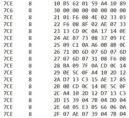
The exchange using Single Frame from the sender and receiver will look like a simple exchange of packets. Exchange using FF, CF, FC frames will look more complicated, this process is more convenient to depict in the diagram below. A series of Consecutive Frames can be followed by a Flow control frame if the transmitted data does not fit into 16 blocks. Or maybe not, it already depends on the specific software implementation of the protocol. Most often, software developers of automotive control units deviate from the formal description of the protocol.

This is an example based on specific data.
Sender ID = 0x7CE
Recipient ID = 0x7C6
The sender sends a data array of size 0xB5 or 181 bytes to the receiver. The image does not show the entire array!
UDS frame
UDS diagnostic protocol frames are built on top of transport frames and look like this:

Where - SID - service identifier. (DTC request, current parameters request, commands...)
PID\LEV – The number of the requested parameter or the number of the function being called.
- The request is sent from the diagnostic equipment to the control unit
- A positive response is sent from the control unit to the diagnostic equipment if the requested parameter is available or the requested function is performed.
- A negative response is sent from the control unit to the diagnostic equipment if the requested parameter is not available, the function cannot be performed, or all conditions for the implementation of the request are not met.
example
Request
CAN ID=0x714 DLC=8 DATA: 03 22 22 06 00 00 00 00
SID = 0x22
PID = 22 06
Positive answer
CAN ID=0x77E DLC=8 DATA: 04 62 22 06 9A 00 00 00
SID+0x40 = 0x62
PID = 22 06
Response parameter = 0x9A
Detailed analysis of specific examples of using the UDS protocol
Example 1. VIN number request
1 Diagnostic tool: ID=0x7E0 DLC=8 DATA: 02 09 02 00 00 00 00 00
2 Vehicle response: ID=0x7E8 DLC=8 DATA: 10 14 49 02 01 57 41 55 “WAU”
3 Diagnostic tool: ID=0x7E0 DLC=8 DATA: 30 02 00 00 00 00 00 00
4 Vehicle response: ID=0x7E8 DLC=8 DATA: 21 5A 5A 5A 38 45 37 37 “ZZZ8E77”
5 Vehicle response: ID=0x7E8 DLC=8 DATA: 22 41 30 37 37 37 37 32 “A077772”
Request from diagnostic device ID=0x7E0 DLC=8 DATA: 02 09 02 00 00 00 00 00
- Byte 0: 02 - Single Frame SF 2 bytes long
- Byte 1: Service ID - SID - Number of the required service. Example: 09 – current settings request.
- Byte 2: Parameter ID – PID – Number of the requested parameter. Example 02 – VIN number request.
ECU response: ID=0x7E8 DLC=8 DATA: 10 14 49 02 01 57 41 55
- Byte 0: 0x10 – FF First Frame or the first frame from a group of subsequent CF frames.
- Byte 1: Message length in bytes. Example 0x14 - 20 bytes transmitted in multiple frames.
- Byte 2: Service ID SID +0x40. Example SID in request = 0x09 and responses = 0x49 . If the service is not supported, byte 2 will take the value =0x7F.
- Byte 3: Parameter ID PID = 0x02
- Bytes 4…7: The value of the requested parameter is returned. 01 57 41 55
Request from diagnostic device ID=0x7E0 DLC=8 DATA: 30 02 00 00 00 00 00 00
Byte 0: 0x30 - Flow control. The command of the control unit to issue all data bytes of the requested parameter in a block of two CF frames with a minimum delay of 0 milliseconds.
ECU response: ID = 0x7E8 DLC = 8 DATA: 21 5A 5A 5A 38 45 37 37
ECU response: ID=0x7E8 DLC=8 DATA: 22 30 37 37 37 37 37 32
Then the control unit gives all data bytes of the requested parameters, which are packed into the required number of CF frames. In the described example, there are two such frames.
Byte 0: 0x21, 0x22 – numbers of CF frames in the series.
Bytes 1…7: Data bytes of the requested parameter.
Example 2. Fuel level request
Let's consider a simpler example - a fuel level request using the UDS protocol in the instrument panel of a VW Touareg NF car.
1 Diagnostic tool: ID=0x714 DLC=8 DATA: 03 22 22 06 00 00 00 00
2 Vehicle response: ID=0x77E DLC=8 DATA: 04 62 22 06 9A 00 00 00
Request from diagnostic device ID=0x714 DLC=8 DATA: 03 22 22 02 00 00 00 00
- Byte 0: Message type and length. Example: 03 – Single Frame SF 3 bytes long
- Byte 1: Service ID - SID - Number of the required service. Example: 22 – current settings request.
- Bytes 2, 3: Parameter ID – PID – Number of the requested parameter. Example 2206 - fuel level request.
ECU response: ID=0x77E DLC=8 DATA: 04 62 22 06 9A 00 00 00
- Byte 0: 0x04 - Single Frame. The length of the message is 4 bytes.
- Byte 1: SID + 0x40 = 0x62 .
- Byte 3,4: PID = 2206
- Byte 4: Return value of the requested parameter = 0x4B – Fuel level = 75 liters .
Example 3. The executive mechanism activation command
As an example of the activation command of the executive mechanism, consider the control of the drive of the central lock of Renault cars.
- Diagnostic tool: ID=0x745 DLC=8 DATA: 02 10 C0 00 00 00 00 00 Opening a diagnostic session
- Vehicle response: ID=0x765 DLC=8 DATA: 02 50 C0 01 00 00 88 00 Confirmation of opening a diagnostic session
- Diagnostic tool: ID=0x745 DLC=8 DATA: 04 30 01 00 00 00 00 00 Command – Close the central lock
- Vehicle response: ID = 0x765 DLC = 8 DATA: 03 70 01 01 00 00 88 00 Command - Closing of the central lock was completed successfully.
In this case, we see the use of two commands: Opening the session and the command to close the lock. Most often, executive control commands require the opening of an extended diagnostic mode session.
If we sent a lock closing command without a session opening command, the response would be: ID=0x765 DLC=8 DATA: 03 7F 30 01 00 00 00 00 , where 7F means that the command cannot be executed.
Table of services available in the UDS protocol
The table presents the services included in the protocol. Not all control units support a full set of services.

Command failure code table
