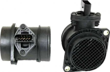
The principle of operation of the air flow sensor MAF Sensor

AvtoAd
28/07/2022
Mass air flow sensor (MSF) is a device for determining the amount of air entering the engine. The air flow regulator transmits information about air consumption to the ECU (electronic control unit), thanks to which it is possible to achieve a stoichiometric ratio of the components of the fuel-air mixture. The air flow regulator is located in the intake system of the internal combustion engine. The place of installation is the section from the air filter to the throttle valve.
Air consumption can be measured:
- mechanical flow meter by volume;
- heat flow meter by mass;
The volumetric air flow sensor is a mechanical volume flow meter that measures the volume of air by estimating the movement of the flap in proportion to the amount of air flow. It is not installed on modern cars.

Air mass flow measurement is performed by DMVP (other names: thermo-anemometric flow meter, air mass flow sensor). The basis of such devices are thermistors. Thermistor is a sensitive element that is prone to heating. For this reason, the device also has another name, a thermal air flow meter.
How the mass air flow sensor works
The principle of operation of different types of DMVP is based on maintaining a constant temperature of the thermistor as a result of heating by electric current. The passage of air through the thermistor causes cooling of the heated element. The mass flow of air is measured due to the fact that the voltage converter converts the heating current into the output voltage. Such voltage and mass air flow have a non-linear relationship. The received data from the sensor is sent to the engine ECU in the form of an analog or digital signal, depending on the design of the sensor. Film-type devices are most widely used today.
In gasoline power units, DMVP is mainly used to determine the moment of fuel injection and the amount of fuel supplied, the moment of spark formation by the ignition system. In diesel engines, DMVP determines the time of fuel injection, and also participates in regulating the working processes of the EGR system.

Types of mass air flow sensors
Most volumetric air flow sensors work according to one of two principles: either the principle of counting Karman vortices is used (some sensors manufactured by MITSUBISHI, CHRISLER...), or the principle of displacement of the potentiometer slider using a blade located in the air flow of the engine. Air flow sensors operating on the principle of counting Karman vortices have high reliability because they do not have moving mechanical parts.
Air volumetric flow sensor, which works on the principle of counting Kármán vortices
The vortex air flow sensor uses the method of counting Karman vortices, which are formed in a laminar air flow, in the path of which there is an obstacle with sharp edges. Air vortices break away from these edges with a frequency that depends linearly on the flow velocity. The sensor works only if there is turbulence in the air flow. Turbulence, in turn, occurs only at a sufficient speed of the air flow. But at very high flow rates, parasitic pressure pulsations may occur. Therefore, some sensors of this type are equipped with an additional input to change the sensitivity of the measuring element, which is necessary if the air flow rate through the air meter is small, for example, when the engine is idling. The first vortex sensors used an ultrasonic transmitter and an ultrasonic receiver. Then there were sensors that use the method of measuring pressure pulsations along the edges of the edges, where vortices of the air flow are formed. In modern vortex air flow sensors, instead of measuring the pressure of pulsations, a thin heated thread is used, and the Kármán vortices are calculated based on the pulsations of its temperature.
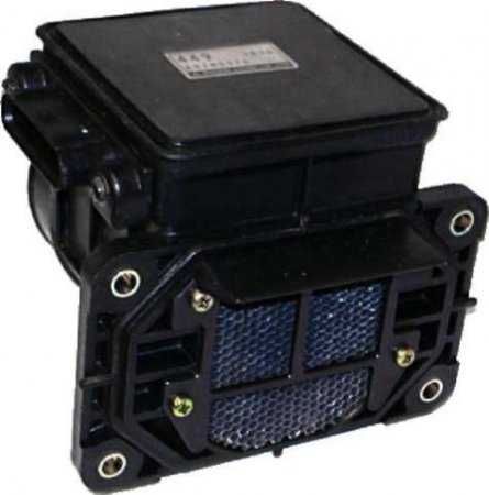
Air volumetric flow sensor with a mechanical measuring potentiometer
Potentiometric-type volumetric air flow sensors work on the principle of displacement of the potentiometer slider with the help of a measuring blade. They have low reliability because their design includes moving mechanical elements. The vane of such a sensor is elastic and is placed in the flow of air flow by the engine so that with an increase in air flow, the vane moves in proportion to the flow. The flow has a pulsating character, and reducing the pulsation effect of the measuring vane will cause pulsations in the air flow, because the sensor vane is connected to the damper. The potentiometer slider is mechanically connected to the measuring blade. The output voltage of this measuring potentiometer is a measure of the volume of air flowing through the sensor. The potentiometer of the volumetric air flow measuring sensor is made on a ceramic substrate. Voltage divider resistors are placed on the substrate, the terminals of which are placed in a row and covered with a resistive contact layer. The slider of the potentiometer is pressed against the resistive contact layer, due to which the voltage on the slider is equal to the voltage at the point of contact with the resistive layer.
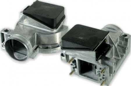
Mass Air Flow Sensor (MAF Sensor)
The measuring element of the air mass flow sensor is a wire or film element heated to a certain set temperature. The flowing air cools this element, but an electrical circuit (usually built into the flow meter) controls its heating power and warms the measuring element to its original temperature. The greater the air flow passing through the flowmeter, the greater the required heating power to maintain the set temperature of the measuring element. Thus, the heating power of the measuring element of the flow meter is a measure of the amount of air flow flowing through the flow sensor. The value of the heating current of the measuring element is converted into the output signal of the sensor - in most cases into an analog voltage, in some types of flowmeters into a rectangular voltage with a changing frequency.
Mass air flow sensor BOSCH HFM5
The output signal of the BOSCH HFM5 mass air flow sensor is a DC voltage varying in the range of 0...5V. The voltage of the output signal of the sensor depends on the magnitude and direction of the air flow passing through the flow sensor. At zero air flow (engine stopped, ignition on), the output voltage of the mass air flow sensor is 1.00V. When the engine is running, air flows through the sensor, and the greater the air flow, the higher the output voltage value of the sensor. At certain engine operating modes, short-term backflows of air may occur - when air moves in the direction from the engine intake manifold to the air filter. The BOSCH HFM5 mass air flow sensor is capable of detecting reverse air flows, while its output voltage decreases to values of less than 1.00 V in proportion to the magnitude of the reverse flow. If the signal from the mass air flow sensor deviates from the norm, the engine operation deteriorates significantly - fuel consumption increases, engine "acceptability" decreases, engine operation becomes unstable at established modes, difficult cold engine start appears. Deviations in the parameters of the output signal can be associated with "deterioration" of the characteristics of the mass air flow sensor, suction of "unaccounted for" air into the intake tract, instability of the sensor's supply voltage. In the case of contamination on the measuring element of the sensor, the speed of the sensor's response to changes in the amount of air flow decreases, as well as the measurement accuracy decreases, which, as a result, leads to the preparation of a fuel-air mixture with the wrong composition. Intensive deposition of dirt on the sensitive element of the sensor can occur due to untimely replacement of the air filter. Sometimes damage to the sensor is observed when the output signal is constantly within 1.00V and changes with increasing air flow. At the same time, the engine starts normally, but immediately stalls. In most cases, the engine control unit can only detect a completely faulty flow meter. "Deterioration" of sensor characteristics is determined by the control unit quite rarely.