Relay-regulator charging in a car, old systems

AvtoAd
06/09/2023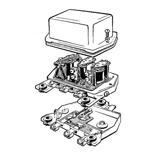
The old relay-regulator constructively combines three devices working in harmony with each other:
Voltage regulator
Maintains a constant voltage of the generator when the number of revolutions of the crankshaft of the engine changes. The current limiter prevents the current from increasing beyond the permissible limit. The reverse current relay connects the generator to the external circuit when the voltage on its brushes is above the battery voltage, and disconnects it when the voltage on the brushes becomes below the battery voltage. Let's consider the device and operation of these devices.
The voltage regulator is an electromagnet consisting of a yoke 9 with a core 8, a winding 7 made of a wire of a strictly selected cross-section, an armature 6 with two contacts 4 and 5, a spring 3, which regulates the force of attraction of the armature, and an additional resistance 2, included in parallel with the contacts .
When the engine is running or idling, ie. when the voltage of the generator is small, the current path is as follows: from the positive brush of the generator along the wire to the winding 7 of the core of the regulator 8 and through the ground to the negative brush of the generator. At the same time, the current flows through the closed contacts 4 and 5 of the armature 6, through the yoke 9 (through point 1) and the excitation winding Ш of the generator to the negative brush of the generator.
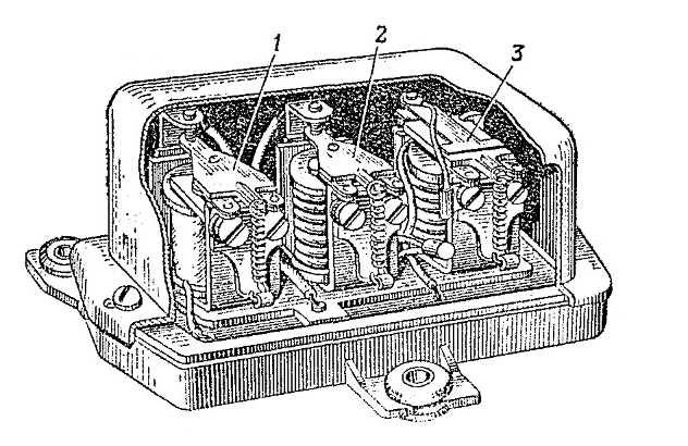
Fig. 1 Relay-regulator: 1 – voltage regulator; 2 - limiter; 3 - reverse current relay
As the number of revolutions of the crankshaft increases, the voltage of the generator increases. When it reaches 14.9, the magnetic flux of the regulator electromagnet increases so much that it overcomes the resistance of the spring 3, attracts the armature 6 and opens contacts 4 and 5. In this case, the current does not flow through the yoke, and an additional resistance 2 is included in the generator excitation winding circuit. As a result, the current and, therefore, the magnetic flux in the excitation winding of the generator decrease, and the voltage of the current supplied by the generator decreases. As soon as the generator voltage drops to 14.1, contacts 4 and 5 of the regulator are closed and the generator voltage begins to rise again.
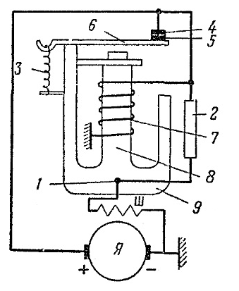
Fig. 2 Voltage regulator scheme: I - generator armature; Ш - excitation winding; 1 - mass of the regulator; 2 - additional resistance; 3 - anchor spring; 4 and 5 - anchor contacts; 6 - anchor; 7 - winding; 8 - core; 9 - yoke
In cars with four-pole generators (Ural-375 cars, etc.), not one but two voltage regulators are used in the relay-regulator. Each of the voltage regulators serves one of the excitation windings of the generator. They are arranged in the same way and work together.
When several current consumers are connected to the external circuit at the same time (headlights, horn, etc.), the current supplied by the generator increases and can increase so much that the generator windings burn out when overloaded.
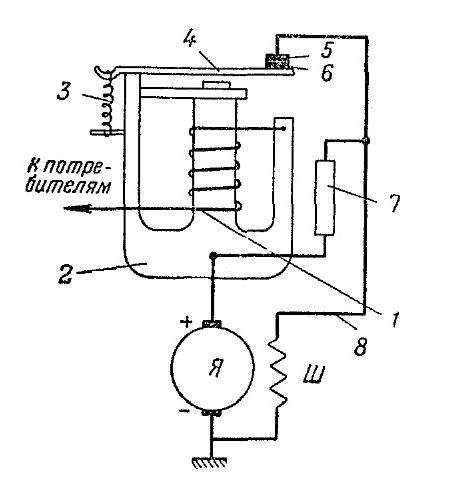
Fig. 3 Scheme of the current limiter: I - generator armature; Ш - excitation winding; 1 - winding; 2 - yoke; 3 - anchor spring; 4 - anchor; 5 and 6 - contacts; 7 - additional resistance; 8 - lead
Current limiter
To prevent overvoltage, a current limiter is used, which works similarly to a voltage regulator, but differs from it in that it has a thick winding, designed for the passage of a current of 17-19 A, instead of a thin one. When the current in the circuit is small, the contacts of the device are closed and the current flows:
a) excitation of the generator: from the positive brush through yoke 2, anchor 4, closed contacts 6 and 5, wire 8, excitation winding Ш and to the negative brush;
b) to the power supply of consumers: from the positive brush through yoke 2, winding 1 of the current limiter, consumers, the mass of the car and to the negative brush.
When the current in the external circuit exceeds 17-19 A, the magnetic field of the core of the current limiter overcomes the tension of spring 3, the core attracts the armature and opens the contacts. Then the excitation current no longer goes through the contacts, but through the additional resistance 7, as a result of which its strength decreases, and therefore, the current supplied by the generator to the external circuit also decreases. Spring 3 due to the weakening of the magnetic field of the core closes contacts 5 and 6, and the excitation current increases again. Thus, as a result of continuous opening and closing of the contacts of the current limiter, the current supplied by the generator is automatically limited to a given value.
Reverse current relay
The reverse current relay is designed to include the generator in the circuit and charge the battery when the voltage from its brushes exceeds the voltage at the battery terminals. When the voltage of the generator operating with a small number of armature turns falls below the battery voltage, the relay disconnects the generator from the external circuit. This is necessary in order to prevent battery discharge through the generator winding and winding burnout.
The reverse current relay consists of a yoke 6, an electromagnet with an armature 5 and two contacts - movable 4 and stationary 3.
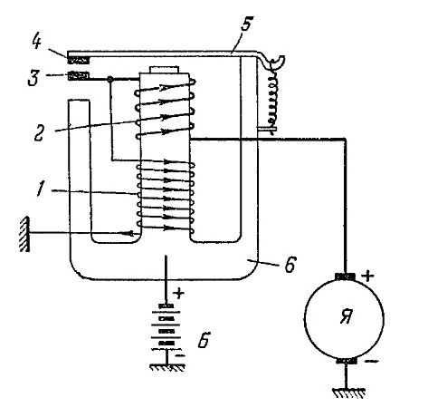
Fig. 4 Reverse current relay scheme: I - generator armature; B - battery; 1 - thin winding; 2 - thick winding; 3 - stationary contact; 4 - movable contact; 5 - anchor; 6 - yoke
The core of the electromagnet has two windings: thick 2 with a small number of turns, connected at one end to the fixed contact 3 and the other to the positive brush of the generator, and thin 1, connected at one end to the mass of the relay-regulator body, and the other to the thick winding.
When the generator voltage becomes less than the battery voltage, the magnetic flux of the core is small and contacts 3 and 4 are open under the action of the spring. As the revolutions of the crankshaft increase, the voltage of the generator increases and when it becomes higher than the voltage of the battery, the relay contacts are closed.
The current path in this case is as follows: from the positive brush of the generator along the wire to the thick winding 2 and through the closed contacts 3 and 4 to the anchor 5, yoke 6 through the battery to the ground of the car and from the ground of the car to the negative brush of the generator; in parallel, part of the current goes through the thin winding and the mass of the car to the negative brush of the generator. At the same time, the current flows in one direction both through the thin and through the thick winding of the relay, increasing the pull of the armature and the density of the contact connection.
When the voltage of the generator becomes less than the voltage of the battery, the current from it goes through the yoke 6, the anchor 5, the closed contacts 4 and 3, the thick winding of the relay 2 and through the generator to the negative terminal of the battery. Since the current flows in the opposite direction through the thick winding, it demagnetizes the core and the contacts open.
The relay-regulator is closed with a cover and sealed. It is usually mounted under the hood on the front wall of the cabin. Three letter-marked terminals protrude from under the cover of the relay-regulator. Terminal B is connected by a wire through an ammeter to a battery; terminals Я and Ш - with the corresponding terminals of the generator. The ground of the relay-regulator (screw on the base) is connected to the ground of the generator (screw on the body).