How turbochargers work on BMW M57TU and M57TU2 engines

AvtoAd
01/04/2023
Information about the turbocharger regulation system on BMW M57TU TOP (pre-restyle engine 272 hp) and M57TU2 TOP (pre-restyle engine 286 hp).
This system can be tricky to understand, especially if you don't work with these vehicles all the time.
First of all, it should be noted that this turbocharger control system is of great importance for the efficiency and performance of the engine. It provides optimal boost pressure, which allows the car to operate at maximum power.
However, if there are problems with this system, it can lead to reduced engine performance and other problems with the vehicle. Therefore, it is important to know how this system works and what features of its work.
M57TU TOP (upgrade to 272 hp) and M57TU2 TOP (upgrade to 286 hp) - work up to 1500 rpm, low load and speed
At the inlet, a large turbine first compresses the air, then it is compressed by a small turbine. The small turbine does the bulk of the work. The whole process effectively affects the responsiveness of the engine.
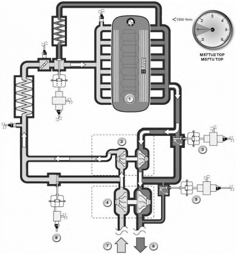
From idle to 1500 rpm
1. Engine
2. Small turbine
3. Turbine control valve
4. Big turbine
5. Wastegate valve
6. Release (to the exhaust)
7. Inlet (from the street)
8. Bypass damper
M57TU2 TOP: 1500 to 3000 rpm (medium load and speed)
M57TU TOP: 1500 to 3250 rpm (medium load and speed)
As the speed increases, the big turbine plays a major role. The engine reaches a maximum torque of 580 Nm from 1750 rpm.
The turbine control valve (hot end) divides the exhaust gas flow between both turbines. The variable position of the turbine control valve allows different operating ranges to be realized and at the same time to regulate the boost pressure.
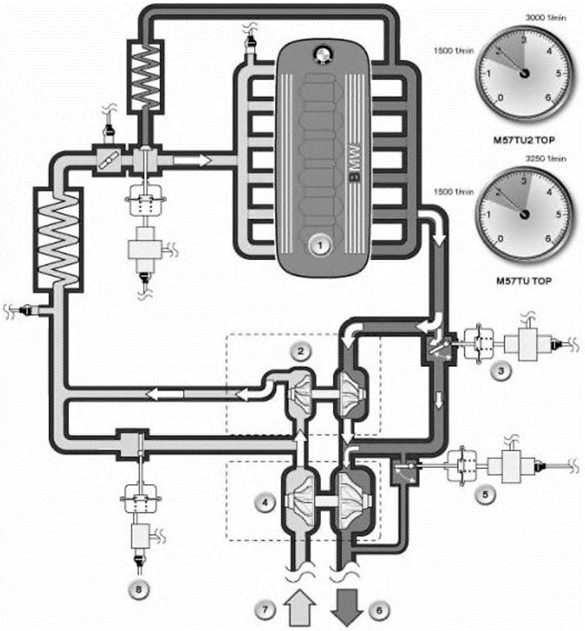
From 1500 to 3000 rpm From 1500 to 3250 rpm Dorest
1. Engine
2. Small turbine
3. Turbine control valve
4. Big turbine
5. Wastegate valve
6. Release (to the exhaust)
7. Inlet (from the street)
8. Bypass damper
M57TU2 TOP: 3000 to 3500 rpm (medium load and speed)
M57TU TOP: 3250 to 4200 rpm (medium load and speed)
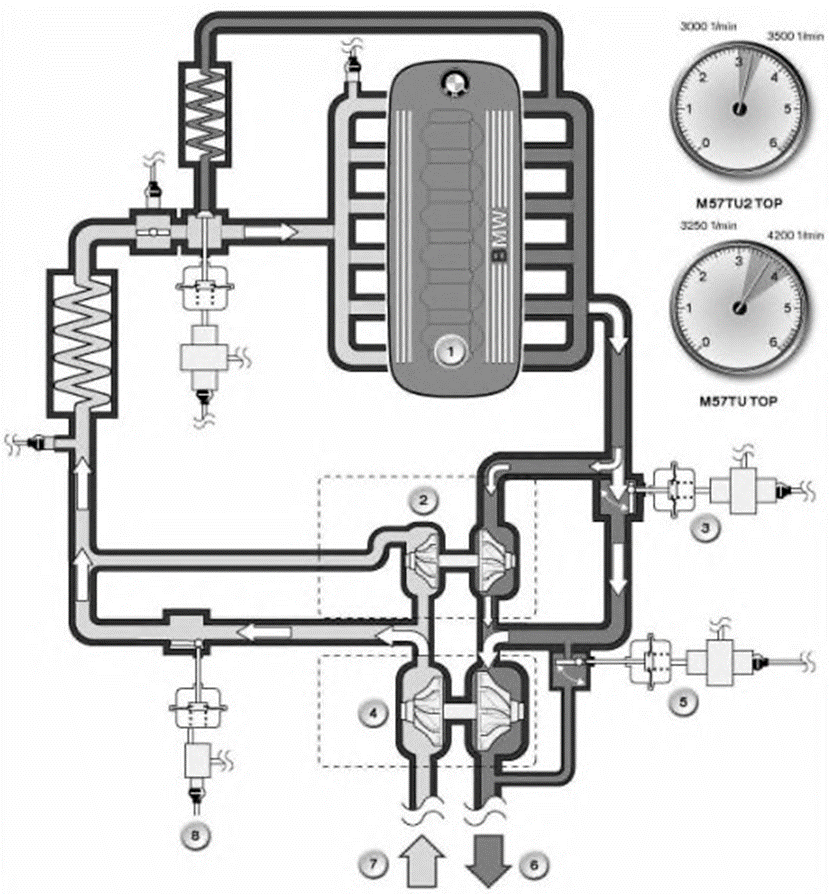
From 3000 to 3500 rpm From 3250 to 4200 rpm Dorest
1. Engine
2. Small turbine
3. Turbine control valve
4. Big turbine
5. Wastegate valve
6. Release (to the exhaust)
7. Inlet (from the street)
8. Bypass damper
M57TU2 TOP: Over 3500 rpm (high load and speed)
M57 TU TOP: Over 4200 rpm (high load and speed)
The small turbine is shut down when the bypass damper and the turbine control valve are fully open.
This allows the large turbine to deliver large volumes of air without being lost to the small turbine.
The work of compressing the air is done by an exceptionally large turbine. The engine reaches its maximum power output of 210kW/286hp. at 4400 rpm (for rest.).
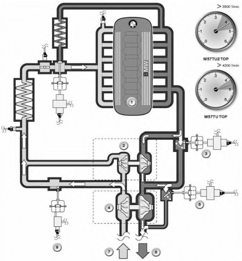
Over 3500 rpm - rest Over 4200 rpm - dorest
1. Engine
2. Small turbine
3. Turbine control valve
4. Big turbine
5. Wastegate valve
6. Release (to the exhaust)
7. Inlet (from the street)
8. Bypass damper
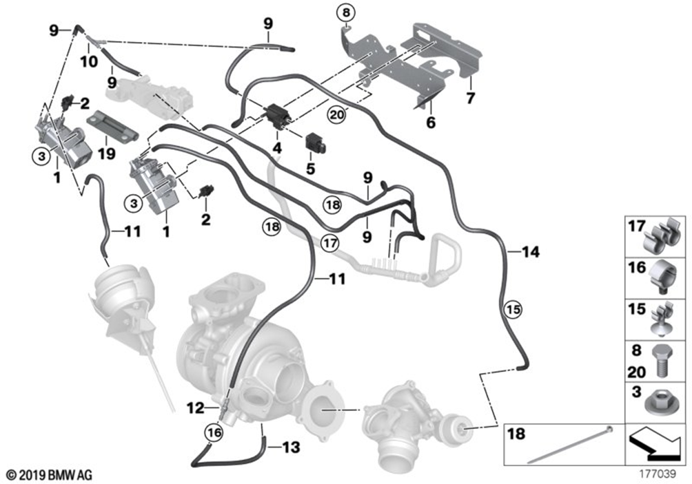
Now let's talk about the M57TU/TU2 TOP vacuum system.
M57TU/TU2 TOP vacuum system consists of various components such as vacuum pump, vacuum tank, vacuum lines, vacuum valves and other parts. These components work together to keep your engine running properly and help you avoid problems.
The most common problems with the M57TU/TU2 TOP vacuum system are vacuum leaks and damaged vacuum lines. These problems can lead to reduced engine performance, increased fuel consumption, and other vehicle problems.
M57TU TOP

M57TU TOP - dorest
1. Electro-pneumatic pressure converter for wastegate valve
2. Electro-pneumatic pressure converter for turbine control valve (hot part)
3. Electric bypass damper control valve
4. Turbine control valve diaphragm (hot end)
5. Turbine (hot part)
6. Wastegate valve diaphragm
7. Vacuum system receiver
8. Bypass valve diaphragm
M57TU2 TOP
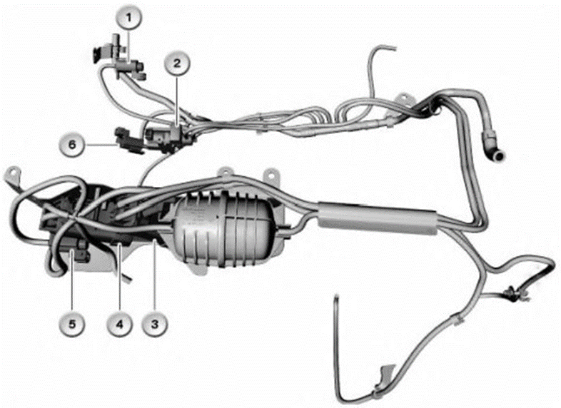
M57TU2 TOP - rest
1. Electrical swirl flap switch
2. Electro-pneumatic pressure converter of the USR system
3. Electro-pneumatic pressure converter of the wastegate valve
4. Electro-pneumatic pressure converter of turbine control valve (hot part)
5. Electrical bypass damper valve
6. Electric motor mount switch
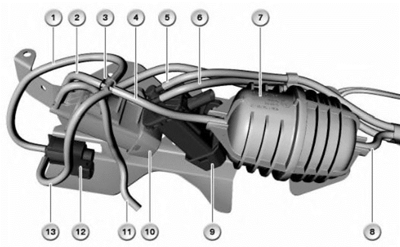
vacuum system
1. Vacuum line, bypass damper
2. Vacuum line, turbine control valve (hot end)
3. Distributor
4. Vacuum line, bypass damper and turbine control valve
5. Vacuum line, wastegate valve
6. Line connection to the wastegate valve
7. Vacuum system receiver
8. Vacuum line, bypass damper and turbine control valve
9. Wastegate valve electro-pneumatic pressure converter
10. Electro-pneumatic pressure converter of the turbine control valve
11. Connection line to the turbine control valve
12. Electrical bypass damper valve
13. Line connecting to the bypass damper
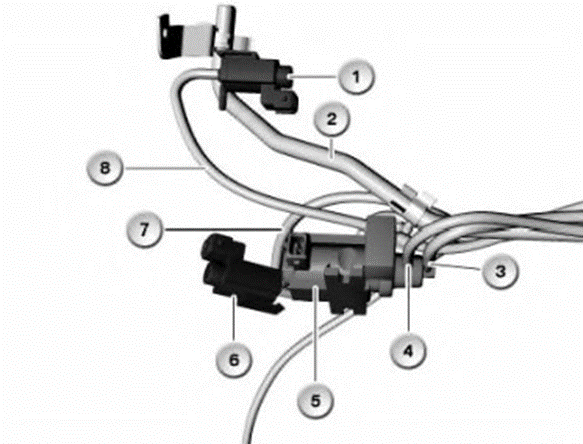
1. Electrical swirl flap switch
2. Vacuum line, brake booster
3. Vacuum line, USR system
4. Line of connection to the USR system
5. Electro-pneumatic pressure converter of the USR system
6. Electric motor mount switch
7. Connecting line to engine mount
8. Vacuum line, swirl flaps
Vacuum System Distributor
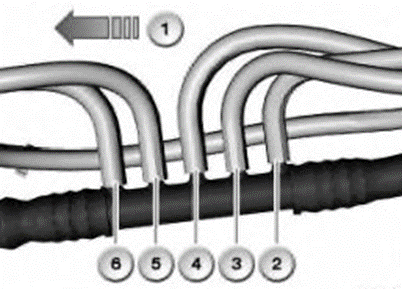
1. Direction of travel
2. Vacuum line, swirl flaps
3. Vacuum line, engine mount
4. Vacuum line, USR
5. Vacuum line, bypass damper and turbine control valve
6. Vacuum line, wastegate valve
M57TU2 TOP is a restyling of the M57TU TOP engine with a two-stage turbocharging system (1 small and 1 large turbine is used).
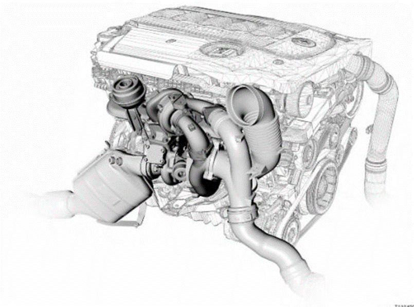
Power has been increased by 10kW/14hp. Began to be used nozzles with piezo elements.
The operation of the M57TU2 TOP features extraordinary output characteristics:
- high torque at low engine speeds
— work in all range of turns of the engine.
Output power 210kW/286hp The peak torque of 580 Nm is reached at 1750 rpm. But 1st, 2nd and reverse gears are limited to 500 Nm.
The two-stage turbocharging system was new to production cars and came from the world of powerful outboard engines. The maximum boost pressure of the entire system is 2.95 bar! The maximum turbine speed is 205,000 rpm for a small turbine and 150,000 rpm for a large turbine (physical limitation), the actual values are lower, which affects the reliability of the turbines.
The M57TU2 TOP engine complies with the EURO4 emission standard. The exhaust system is equipped with a particulate filter.
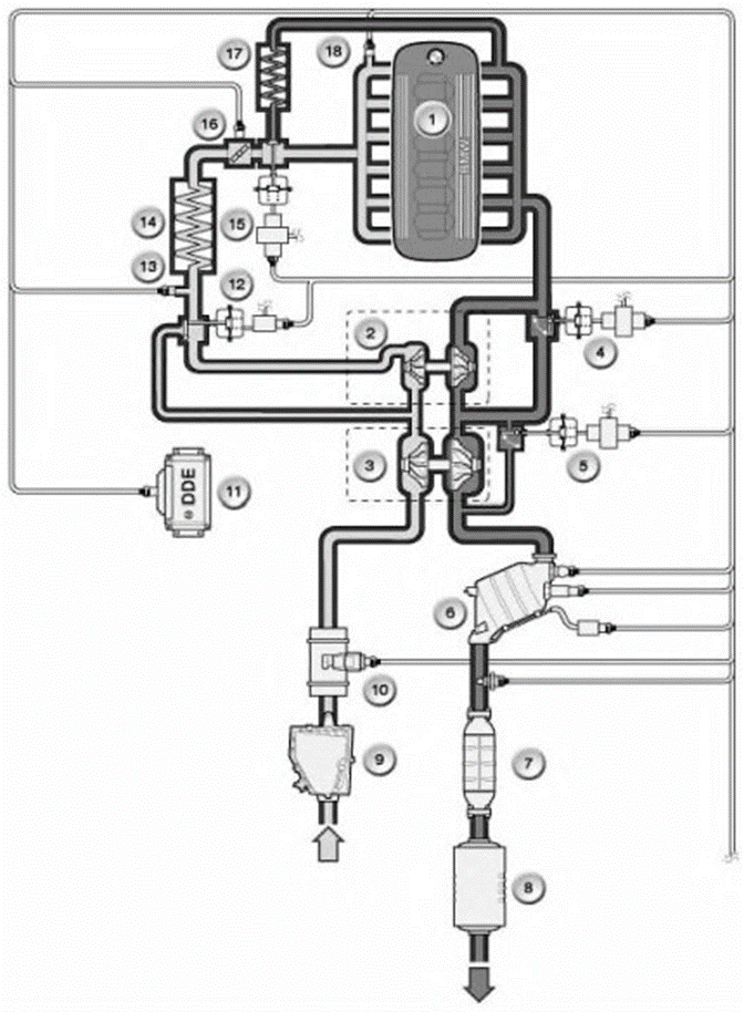
General scheme
1. Engine
2. Small turbine
3. Big turbine
4. Turbine control valve (hot part)
5. Wastegate valve
6. Catalyst
7. Particulate filter
8. Silencer bank
9. Air intake silencer
10. Air flow meter
11. Engine control unit
12. Bypass damper
13. Boost air temperature sensor
14. Intercooler
15. EGR valve
16. Electronic throttle
17. EGR exhaust gas cooler
18. Boost pressure sensor
The most important components for a two-stage turbocharging system are:

Two-stage pressurization system M57TU TOP - dorest.
1. Exhaust manifold
2. Turbine control valve (hot part)
3. Small turbine
4. Fresh air (filter side inlet)
5. Compressed air towards the intercooler
6. Bypass damper
7. Big turbine
8. Wastegate valve
9. Release

Two-stage pressurization system M57TU2 TOP - rest.
1. Exhaust manifold
2. Turbine control valve (hot part)
3. Small turbine
4. Fresh air (filter side inlet)
5. Compressed air towards the intercooler
6. Bypass damper
7. Big turbine
8. Release
- 1 small turbine
Turbine size has a decisive influence on engine performance (power and responsiveness).
Due to its low mass, which is accelerated by the exhaust gases, the small turbine becomes extremely responsive. Boost pressure appears very quickly when the throttle is opened, which means the engine responds with much less delay.
- 1 large turbine
When the throttle is open, the exhaust gases accelerate the large mass of the turbine, so the engine responds slowly. However, when high pressure and high air flow results are required, the large cross-sectional area of the turbine is more efficient.
In a two-stage turbocharging system, 2 turbines are arranged in series. Exhaust gases first spin the small turbine, then the large one. On the intake side, the air is first compressed by a large turbine, then a small one.
- Turbine control valve (hot part)
The turbine control valve regulates the distribution of the exhaust gas flow between the small and large turbines. The turbine control valve is pneumatically controlled by a diaphragm ("mushroom", approx.), The adjustment has a variable value and changes depending on the pressure in the diaphragm with a vacuum.
- Bypass damper of the cold part of the turbine (Bypass)
The bypass allows the air flow to bypass the cold part of the small turbine, which is pneumatically controlled by a diaphragm. It can be either completely open or completely closed. An electric valve charges the diaphragm with a vacuum.
- Unloader valve (Westgate)
After the nominal value has been reached, the wastegate valve is opened to avoid excessively high boost pressure. Part of the exhaust gases is fed through the unloader valve past the hot part of the large turbine. The wastegate is pneumatically controlled by a diaphragm and can be partially opened/closed. The control diaphragm is charged with vacuum through an electro-pneumatic pressure regulator.
Turbines have a variable geometry of the hot part. Both turbines are constantly running.

If you notice any signs of problems with the M57TU/TU2 TOP vacuum system, such as improper engine operation, reduced power, or low system pressure, you should immediately contact an experienced auto repair technician. They will be able to diagnose the system and solve any problems that arise.