Common Rail fuel system - what is it?
AvtoAd
18/01/2023
Content
1. Common Rail power supply system of a diesel engine.
1.1. Common Rail injection system.
1.2. The principle of operation of the Common Rail injection system.
1.3. Multiple injection in the Common Rail system.
1.4. Advantages and disadvantages of the Common Rail system.
1.5. Prospects for the development of the Common Rail food system.
2. COMMON RAIL ENGINE: PRINCIPLE OF OPERATION, RELIABILITY, MAINTENANCE, PROS AND CONS.
3. Common Rail fuel system. The principle of operation and features.
4. Features of the device and advantages of the Common Rail fuel system.
4.1. What is a common rail fuel system.
4.2. Features and principle of operation.
4.3. Advantages and disadvantages of the Common Rail system.
6. The principle of operation of the diesel system.
7. DEVICE AND PRINCIPLE OF OPERATION OF THE COMMON RAIL SYSTEM.
8. How the Common Rail injection system works.
8.1. Individual solutions for flexible fuel use.
9. Components, working principle and functions - Punch Newspapers.
10. Common Rail direct injection.
11. Principle of operation of CRDi .
13. FUEL SYSTEM: COMPONENTS, OPERATING PRINCIPLES, SYMPTOMS AND EMISSION CONTROL.
14. Common Rail injection system.
Common Rail power supply system of a diesel engine
Common Rail injection system (Common Rail translated from English - "common path", "common ramp") is a modern fuel injection system of diesel engines. However, an analogue of such a system is also used in gasoline engines with forced fuel injection, i.e. injection engines.
The developers of the Common Rail system are specialists from the well-known German company Bosch. Such systems appeared in 1997 on mass-produced cars with electronic control. At present, work on the application of Common Rail systems is carried out by almost all TPA manufacturers (R.Bosch, Lucas, Siemens, L'Orange).
The main fundamental difference between the Common Rail system and the considered previous article of the classical power system is that fuel is supplied to the injectors directly from the injection pump, as from a common accumulator - a fuel ramp.
Common Rail injection system

The fuel ramp (fuel accumulator) is a thick-walled cylindrical vessel capable of withstanding the high pressure developed by the injection pump. A constant fuel pressure is maintained in the ramp by means of a fuel injection pump and a pressure regulator, and each injector is connected to the ramp by a fuel line.
At the right moment, the control unit generates a control signal for the electromagnetic (or piezoelectric) nozzle valve, the nozzle opens and fuel is injected into the cylinder.
Thus, the main difference of the Common Rail system is the separation of the processes of creating pressure and fuel injection, which allows you to get a number of advantages in operation.
The use of this system allows you to reduce fuel consumption, exhaust gas toxicity, diesel noise level, and also significantly improve its dynamic characteristics. Compared to a conventional diesel, the system
Common Rail allows you to reduce fuel consumption by up to 40% while reducing the toxicity of exhaust gases and reducing noise during operation by 10%.

The main advantage of the Common Rail system is the ability to control fuel supply using a computer (electronic control unit), which allows for a wide range of regulation of pressure, quantity and moment of fuel injection.
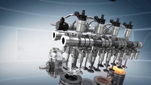
Structurally, the Common Rail injection system is a high-pressure circuit of the fuel system of a classic diesel engine. The system uses direct fuel injection, i.e. diesel fuel is injected directly into the combustion chamber.
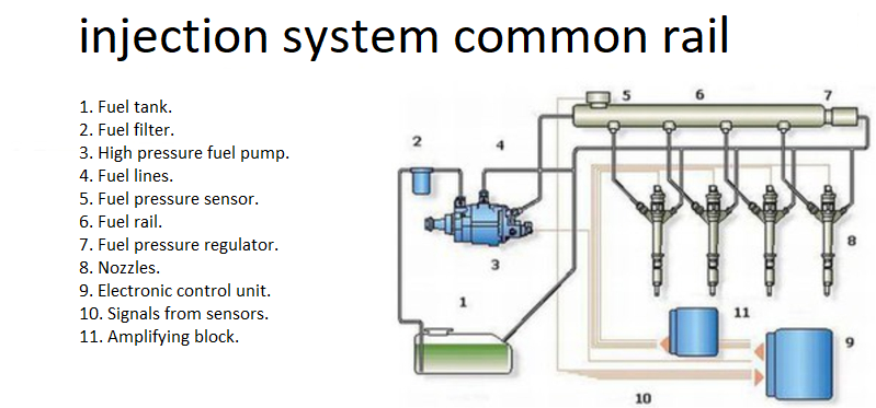
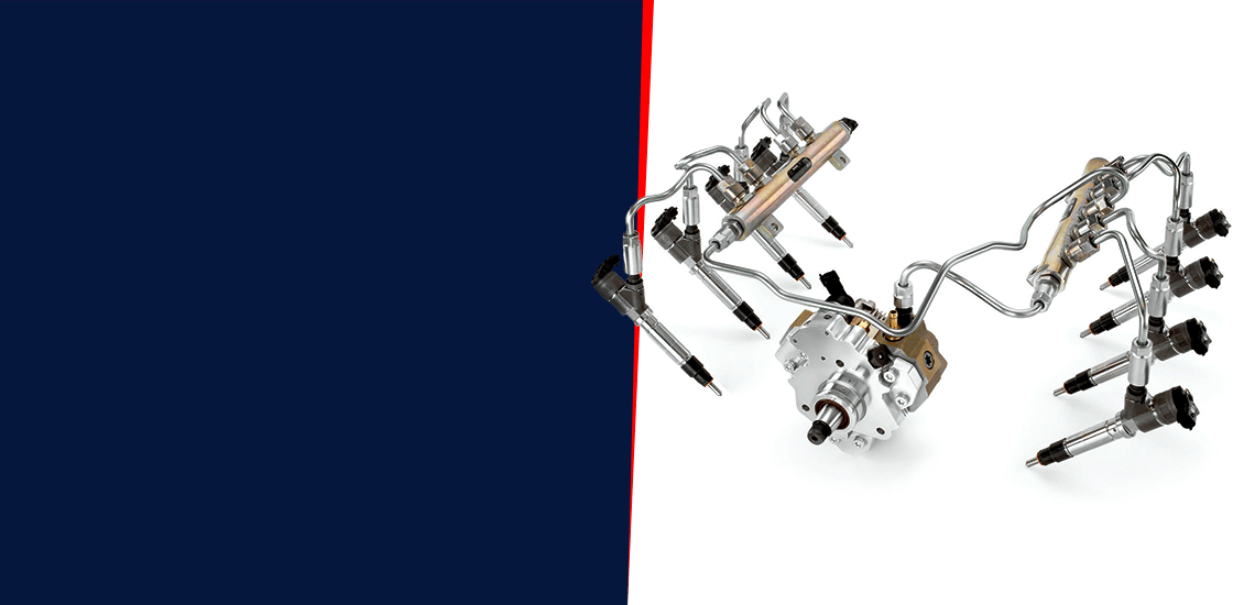
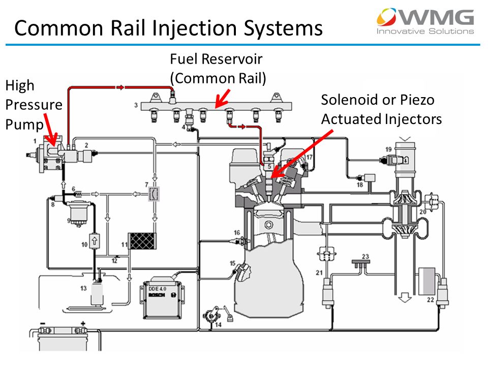
The Common Rail system includes a high pressure fuel pump, fuel metering valve, fuel pressure regulator (check valve), fuel rail and injectors. All elements connect fuel lines.
The high-pressure fuel pump (HPV) serves to create high fuel pressure and accumulate it in the fuel rail. High-pressure radial-piston or plunger-type fuel pumps are used on modern diesel engines equipped with a Common Rail power supply system.

The fuel metering valve regulates the amount of fuel delivered to the high pressure fuel pump based on engine demand. The valve is structurally connected to the injection pump.
The fuel pressure regulator is designed to control the fuel pressure in the system depending on the engine load. It is installed in the fuel rail.
The fuel ramp is designed to perform several functions: accumulation of fuel and its content under high pressure, softening of pressure fluctuations arising as a result of pulsation of the supply from the injection pump, distribution of fuel by nozzles.
The injector is the most important element of the system that directly injects fuel into the engine's combustion chamber. The injectors are connected to the fuel rail by high-pressure fuel lines. Electrohydraulic nozzles or piezo nozzles are used in the system.
Fuel injection with an electrohydraulic injector is carried out by controlling an electromagnetic valve. The active element of the piezo nozzle is piezo crystals, which significantly increase the speed of the nozzle.

Control of the operation of the Common Rail injection system is provided by the diesel control system, which combines sensors, the engine control unit and the actuators of the engine systems. The main executive mechanisms of the injection system
Common Rail has injectors, a fuel metering valve, and a fuel pressure regulator.
The principle of operation of the Common Rail injection system
The working principle of the Common Rail power supply system is quite simple, and attempts to use it have been known for a long time - more than half a century ago. Nevertheless, the maximum effect from the use of such a power system can be obtained only with the help of computer control of the engine, so such systems have only recently become widespread.
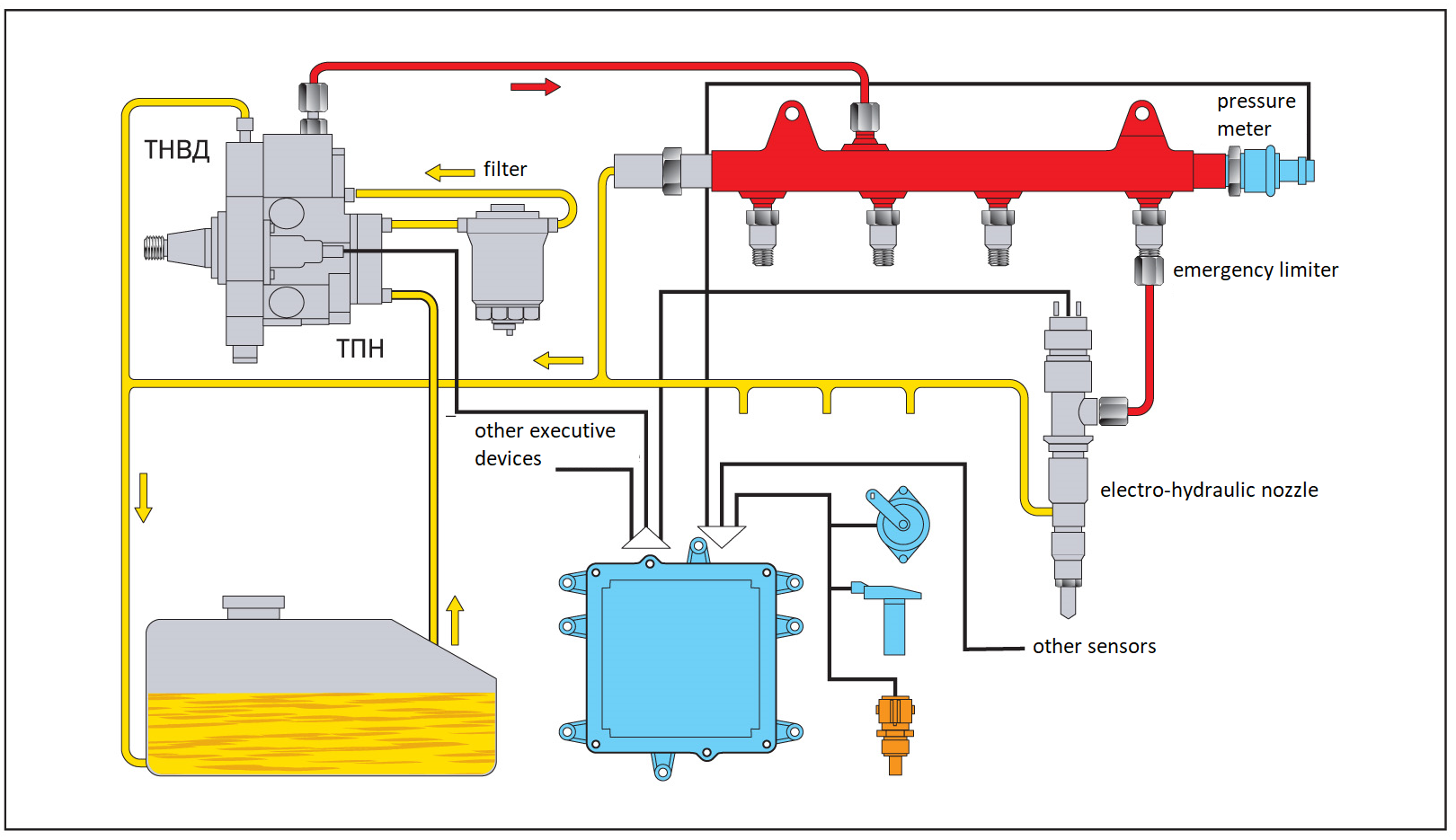
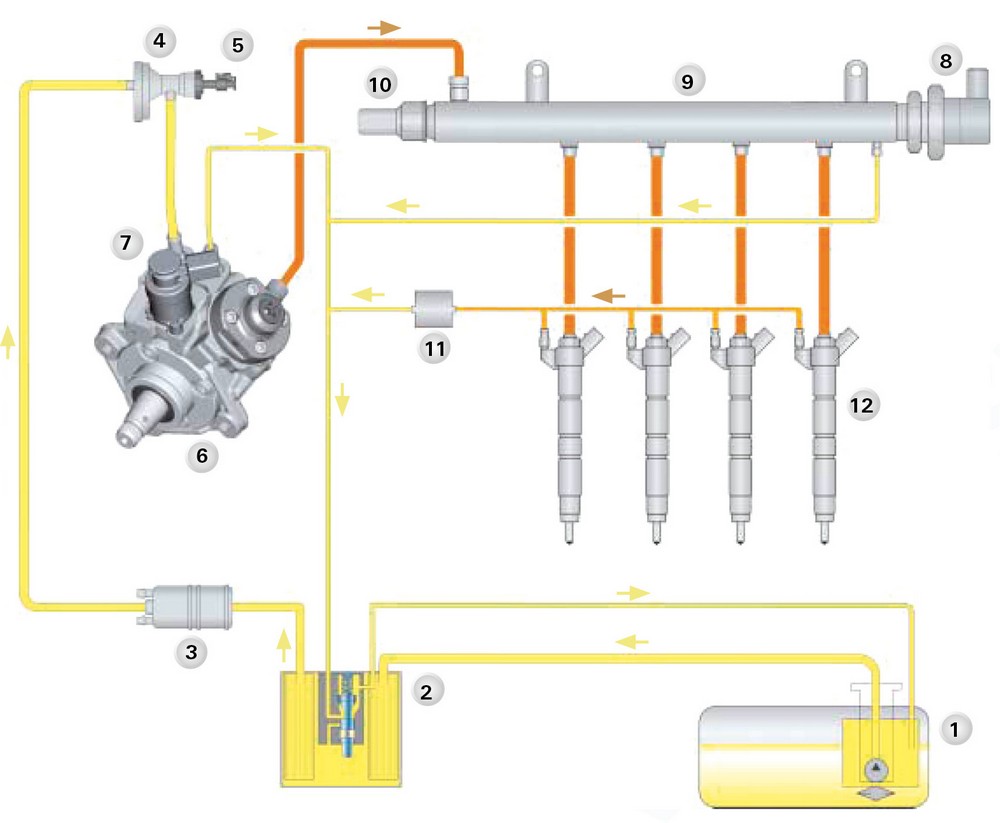
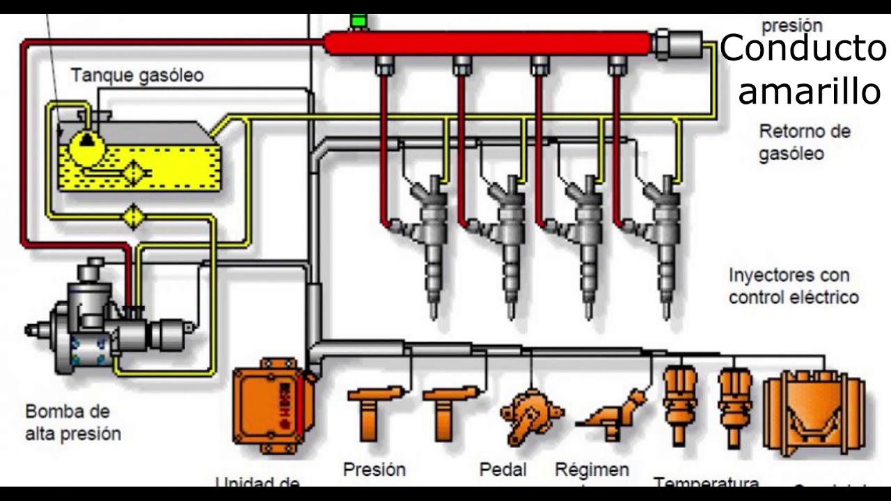
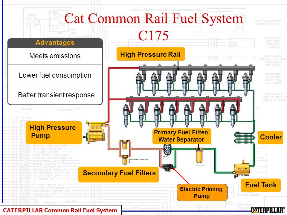
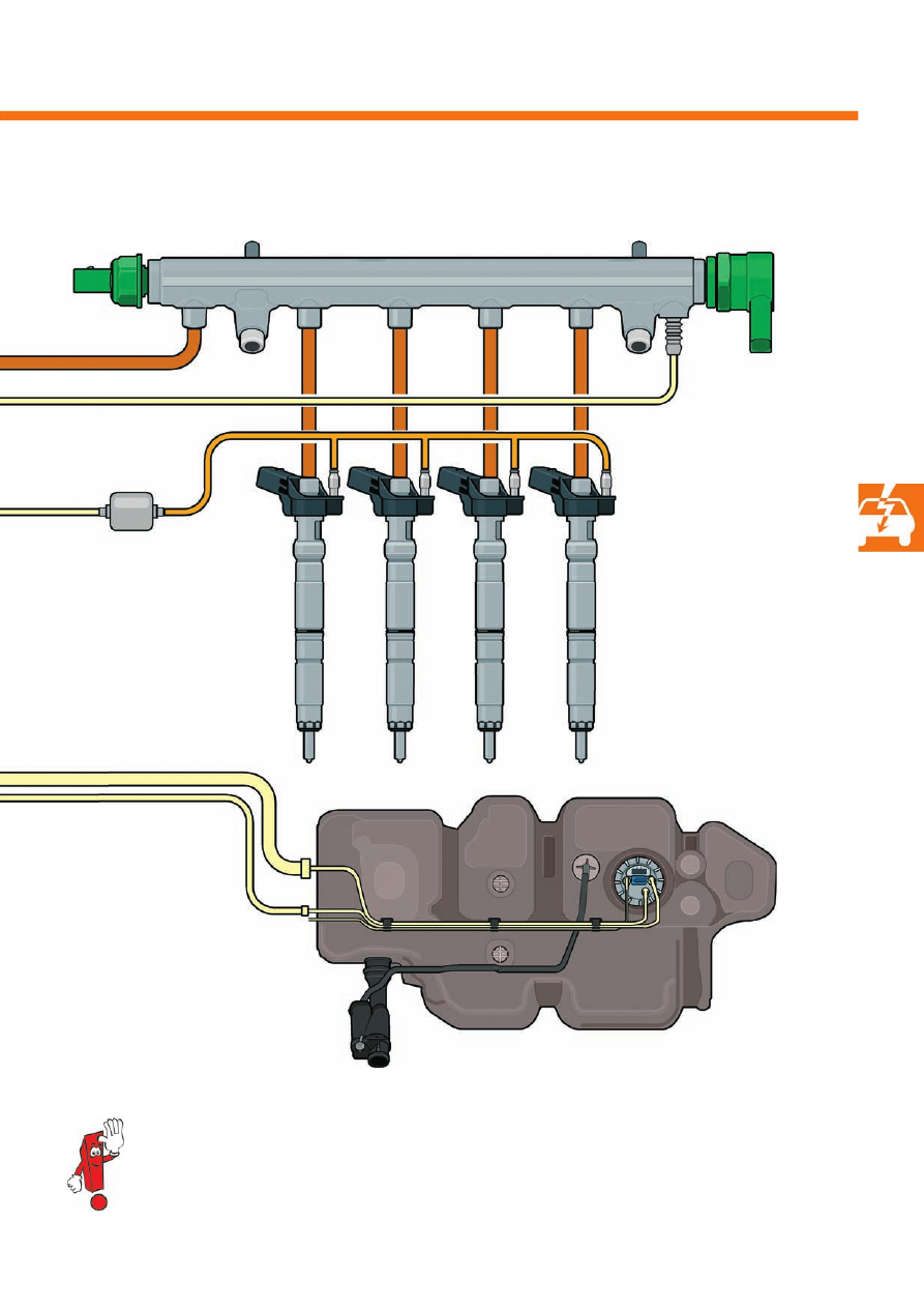
Let's consider in more detail the operation of Common Rail on the diagram below.
With the help of a fuel injection pump (TPN), fuel is pumped from the fuel tank and fed through a filter with a moisture separator to a high-pressure radial plunger pump.
(TNVD), which uses an eccentric shaft to move three plungers. The high-pressure fuel pump is directly connected to the camshaft and delivers a portion of fuel to the ramp at each revolution, rather than once every two revolutions in a conventional engine. From the high-pressure fuel pump, fuel under high pressure enters the hydraulic accumulator (fuel ramp), from where it is fed to the electro- or piezo-hydraulic nozzles controlled by the computer. Surplus fuel from the injectors and injection pump drains into the fuel tank through the drain fuel lines (return drain line).
At the right moment, the control unit (ECU) gives the command to the corresponding injectors to start injection and provides a certain duration of opening of the injector valve.
Depending on the engine operating modes, the engine control unit adjusts the operation parameters of the injection system.
The start of injection and the amount of fuel supplied to the engine cylinders through the injectors depends on the start and duration of the signal of the electronic control unit, which is formed on the basis of information from the sensors. This signal depends on several parameters, primarily on the engine operating mode. The diesel control system includes sensors for engine speed, crankshaft position (Hall sensor), accelerator pedal position, air flow meter, coolant temperature, air pressure, air temperature, fuel pressure, oxygen sensor (lambda probe) and some others.
The pressure in the system is regulated by a signal from the control unit using a regulator. It is minimal on single stroke, which reduces the noise of the injectors and high pressure fuel injection, and at acceleration it is maximal to ensure better reception.
Multiple injection in the Common Rail system
Since the injection pressure is independent of engine speed and load, the actual start, pressure and duration of the injection can be freely selected within a wide range of values.
photo
In addition, there is the possibility of using pre-injection (or even several injections), regulated depending on the needs of the engine, which leads to a significant reduction in engine noise along with improving the combustion process and reducing the emission of harmful substances with exhaust gases.
In order to increase the efficient operation of the engine, the Common Rail system implements multiple fuel injection during one engine operation cycle. At the same time, they are distinguished: preliminary injection, main injection and additional injection.
Pre-injection of a small amount of fuel is carried out before the main injection to increase the temperature and pressure in the combustion chamber, thereby accelerating the self-ignition of the main charge, reducing the noise and toxicity of the exhaust gases. Depending on the engine operating mode, the following is performed:
- two previous injections - at idle;
- one preliminary injection - when the load increases;
- preliminary injection is not carried out - at full load;
- the main injection ensures the operation of the engine in the mode of partial and nominal loads.

Additional injection is carried out to increase the temperature of the exhaust gases and the combustion of soot particles in the soot filter (soot filter regeneration).
Advantages and disadvantages of the Common Rail system
As already mentioned above, the use of the Common Rail power supply system in diesel engines instead of the classic power supply system gives a noticeable increase in power, environmental friendliness and economy of the engine. Reduction of fuel consumption, emission of harmful substances, noise, along with increase of dynamic indicators, is achieved by the possibility of computer control of all injection processes, which is impossible to implement in traditional power systems, even the most complex and advanced ones.
The significant disadvantages of the Common Rail system include the complexity of maintenance, which requires highly qualified technical personnel and the need to use special equipment for testing the system. Therefore, if the car is operated in conditions of limited technical service of a low level, it is more reliable to use a classic power system.
It should be noted that the Common Rail power system exposes the engine oil to significant thermal loads. Due to more intensive combustion, the upper part (head) of the pistons heats up much more than in a classic diesel engine. If the piston head of a classic direct injection diesel engine heats up to 320-350 ° C, when working with a common rail power system - more than 400 ° C. As a result, engine oil burns out and oxidizes much more intensively. For this reason, it is necessary to use synthetic or semi-synthetic motor oils in the lubrication system of diesels with Common Rail injection.
Prospects for the development of the Common Rail food system
The improvement of the Common Rail power system is carried out by increasing the injection pressure. It is obvious that the higher the pressure in the system at the time of injection, the more fuel manages to get into the cylinder in the same amount of time and, accordingly, realize greater engine power. In addition, injection under high pressure ensures high quality atomization of fuel by the nozzle, which has a beneficial effect on the processes of mixture formation and combustion.
In modern engines, the increase in injection pressure is limited by the strength of the fuel accumulator (ramp) and high-pressure fuel lines, which are prone to pulsating and vibrational loads during engine operation and can collapse.
Nevertheless, over a decade and a half, engineering solutions managed to increase the injection pressure by more than one and a half times - in modern diesels with a Common Rail power system, it reaches 220 MPa and even more.
COMMON RAIL ENGINE: PRINCIPLE OF OPERATION, RELIABILITY, MAINTENANCE, PROS AND CONS.
In order to understand how the automotive system with high-pressure fuel injection technology (Common Rail) functions, it is necessary to know its design features, what elements it consists of, as well as what functions and tasks it performs in a particular vehicle power plant. We will discuss these questions in our story in order to get a comprehensive idea of the working principle of the Common Rail automotive fuel system. In addition, consider the question that is often asked by many car owners: "How does the high-pressure fuel injection system differ from classic fuel technologies?".
1. Features, pros and cons of the Common Rail fuel injection system
The Common Rail system is a fuel injection technology for diesel power plants. The principle of operation is based on the supply of fuel to the nozzles under constant pressure from the common ramp. This technology was first developed by German engineers of the Bosch company. Common Rail from Bosch is widely used in vehicles from brands such as Volvo, Mercedes-Benz and BMW.

The Common Rail fuel system translated from English means the common highway of the fuel mechanism of the vehicle. Such a system is characterized by fuel injection into the combustion chamber of cylinders under high atmospheric pressure. Thanks to the supply of fuel under pressure to the cylinders, high efficiency of the power plant is ensured and fuel consumption is reduced by an average of 10-15%, and engine power increases by approximately 30-40%.
In addition to increasing power plant power and reducing fuel consumption, the benefits of the Common Rail high-pressure injection system do not end there. This system is characterized by a reduction in engine noise, while the turning torque of the diesel engine increases by an average of 5-10 percent. Thanks to the factors described above, the Common Rail fuel injection system has gained general popularity and today approximately every second car on the planet with a diesel power plant is equipped with this technology.
Among the shortcomings of the Common Rail system, it is possible to single out fairly high quality standards for the diesel fuel consumed. In the event that small foreign particles in the form of undissolved paraffin, which is contained in the diesel engine, enter such a fuel system, it can lead to the failure of the electronically controlled and high-precision injectors. That is why in diesel power plants with the Common Rail system, the use of high-quality diesel fuel is the most important and mandatory condition.
2. The principle of operation of the Common Rail fuel injection system
The main principle of operation of the Common Rail system is to supply fuel, as a rule, of diesel type, to the nozzles from a common ramp under high pressure. The pressure in such an injection system is generated and maintained regardless of the rotational speed of the crankshaft of the state power plant. In addition, the pressure in the fuel system of this type is also not affected by the parameter of the volume of fuel injected into the cylinder chambers.
The fuel injection process is carried out by injectors under a special command of the electronic control unit of the system. Magnetic solenoids are built into each injector, which are turned on from the same electronic control unit of the injection system. Thus, with the help of "smart" nozzles, a controlled injection of fuel into the combustion chambers of the fuel-air mixture located in the engine cylinders is formed.

To improve the efficiency of the Common Rail injection system, it was decided to develop and use a special unit called the battery unit, which includes a distribution pipeline, fuel supply pipes, and the injectors themselves. The electronic control unit transmits a control signal to the injectors, or rather to the solenoids, which are installed on these parts, according to the program embedded in it.
Next, the solenoids, under the command of the control unit, supply diesel fuel to the combustion chambers of the engine's fuel-air mixture with the help of actuators in the form of nozzles. The whole procedure is based on the principle of separation of the unit, which creates high pressure and injection elements, which ensure an increase in the accuracy of control of the combustion process of the mixture and an increase in the power of fuel supply.
3. Device and design differences of the Common Rail system
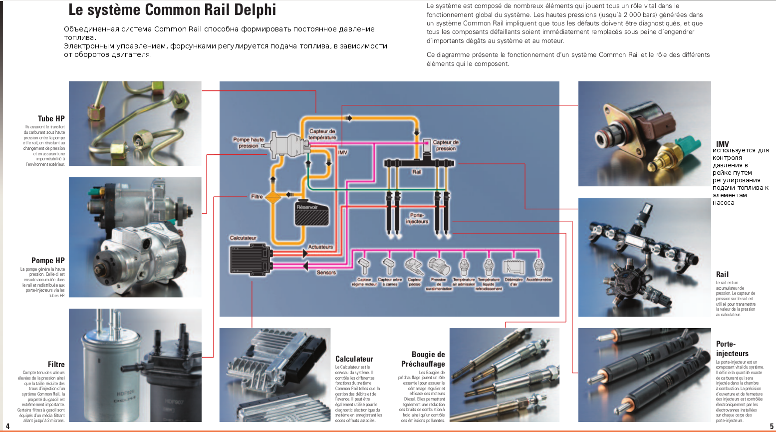
The Common Rail system is significantly different from classic fuel systems, for example, FSI or GDI. The injection system operates under high pressure Common Rail and includes 3 main components, such as:
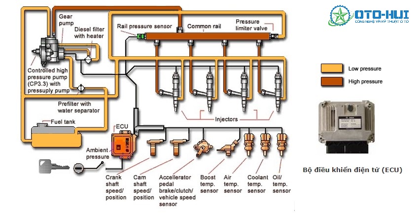
– Low-pressure circuit: includes a fuel tank, a pump with a fuel injection type of action, a filter element and pipelines for connecting the system parts.
– High-pressure circuit: it consists of a high-pressure pump, which replaces a classic high-pressure pump with a control-registration valve, a high-pressure ramp with a sensor that monitors the working pressure in it, injectors with solenoids, and connecting hoses with pipelines. For reference, we note that the high-pressure ramp is a long pipe with transversely installed fittings for connection with nozzles and is made in the form of a two-layer element.
– Special system sensors: located throughout the fuel system to control, register and send the collected information to the electronic unit. There are about a dozen such sensors in the Common Rail system.

The electronic type unit of the Common Rail system receives certain electrical signals from sensors such as crankshaft position, camshaft position, accelerator pedal movement, boost pressure, as well as ambient air temperature, antifreeze temperature, mass air flow and fuel pressure. The electronic control unit of the Common Rail system, based on the signals and information provided to it from various sensors, analyzes and then calculates the required amount of fuel mixture supplied to the engine cylinder chambers.

After calculating the data, the control unit sends a command to start injecting the required amount of fuel to such executive elements as injectors. Injectors are turned on through received signals to solenoids. In addition, the control unit determines the duration of the opening of the nozzles, adjusts the injection indicators, and also manages the operation of the entire system as a whole.
The low-pressure circuit of the system provides, with the help of a special pump, suction and pumping of fuel from the gas tank of the car, then fuel is passed through a filtering element, in which unnecessary impurities in the form of paraffin settle, and then the filtered mixture is delivered to the circuit with high working pressure.
When fuel enters the circuit with high operating pressure, the pump directs the combustible mixture to the battery unit, where it is under pressure in the range of 120-140 MegaPascals using a control valve. In the event that this valve is opened at the command of the electronic unit, then the fuel from the pump is sent to the gas tank through the drain pipe. Note that each nozzle is connected to the battery unit by special separate high-pressure tubes. Inside the nozzle itself, as mentioned earlier, there is a control solenoid, also known as an electromagnetic type valve.
Further along the chain, after receiving an electrical signal from the electronic control unit of the Common Rail system, the injector injects fuel into a certain cylinder of the power plant. The duration of fuel injection is carried out until the injector solenoid turns off according to the command received from the same electronic control unit, which in turn calculates and determines the moment of the start of injection, the amount of fuel, receiving information from various sensors and analyzing the received indicators with the help of special software security embedded in the memory of the processor or computer at the manufacturing plant.
In addition, the electronic control unit also systematically monitors the performance of the entire Common Rail system. Since in the battery unit, the fuel is at a consistently high pressure, this makes it possible to inject small and well-measured portions of fuel. In addition, in modern Common Rail systems, the function of supplying the previous part of the fuel before the main injection has appeared. This possibility provided an improved combustion process of the fuel-air mixture in the cylinder chambers of the car engine.
In conclusion, we note that thanks to the high-precision electronic control and optimal pressure in the Common Rail fuel injection system, fuel combustion in the power plant is carried out with maximum efficiency, which ensures comfortable operation of the car engine, since optimal indicators are achieved in each of the modes of the power plant. Thanks to these factors, fuel consumption is reduced and the toxicity of exhaust gases in the vehicle's exhaust system is reduced. Thus, the common rail high-pressure fuel injection fuel system has ensured the development of a whole generation of diesel engines, because it has inexhaustible potential. Since the environmental standards for toxicity are increasing every year, this primarily contributes to the further rapid development of fuel systems based on Common Rail technology.
Common Rail fuel system. The principle of operation and features.
The common rail high pressure fuel system is superior to today's diesel engines, far surpassing the mechanical and hydraulic injection systems of yesteryear. With relatively high injection pressure and greater control over injector events, Common Rail injection systems have good performance and lower emissions while increasing efficiency.

fuel is fed from the fuel tank to the fuel pump via the lift pump. The sole purpose of the lift pump is to constantly feed fuel to the fuel pump - the fuel pressure entering the fuel pump has little or no effect on the actual pressure coming out of the injector nozzle. The high pressure pump maintains enormous pressure in the common rail/s (an I-6 (in-line) engine has one common fuel rail feeding each injector, while a "V" (V-shaped) engine will use two common rails, one for each row of cylinders). The pressure in the ramp or the pressure in the fuel system at the outlet of the high pressure pump can reach pressures in excess of 2000 bar.
The injection events are controlled by the PCM / ECM module which supplies power to the injector to initiate the injection event. When this happens, the fuel passes through the injector nozzle and is sprayed into the combustion chamber. The most important factor in a Common Rail system is rail pressure - higher rail pressure results in more fuel atomization and is therefore closely related to combustion efficiency.
The Common Rail system is an alternative to mechanical injectors and HEUI systems, which, unlike the latter two, has the ability to implement a relatively high injection pressure and start the injector several times in one combustion event (the ability to pre-inject a small amount of fuel into the cylinder to increase the temperature and pressure in the chamber combustion, which achieves accelerated ignition of the main charge, as well as additional injection after the main increase in the temperature of the exhaust gases and the combustion of soot particles in the soot filter). This leads to increased productivity potential, reduced emissions and increased efficiency. Common rail systems also typically reduce engine noise.

However, despite all the advantages of this system, there are some disadvantages. First of all, due to the higher pressure of the system, and therefore higher loads on the cylinder-piston group of the engine, owners of Common Rail systems should use high-quality engine oils and replace them at least once every 8-9 thousand kilometers. You should also take care of refueling only with high-quality diesel fuel, the presence of foreign impurities, dirt and water in the diesel engine can quickly disable the fuel system. Another disadvantage compared to other systems is the more expensive repair, which must be carried out by qualified personnel using special tools and a bench for adjusting the injection pump.
Features of the device and advantages of the Common Rail fuel system
The Common Rail fuel system is used exclusively in diesel engines and is considered the most advanced at the moment. Compared to other schemes, it provides more economical fuel consumption, increases the environmental safety of the car, has a low noise level, but most importantly - creates a higher supply pressure to the combustion chamber. How the Common Rail injection system is arranged and the principles of its operation will be discussed further.
What is a common rail fuel system
Literally, the term Common Rail is translated into Russian as a common highway. The main design feature of this system is the presence of a fuel ramp in which fuel is accumulated before being fed to the diesel engine nozzles. Due to this feature, such systems are also called battery-powered. It was first introduced by Bosch in 1996.
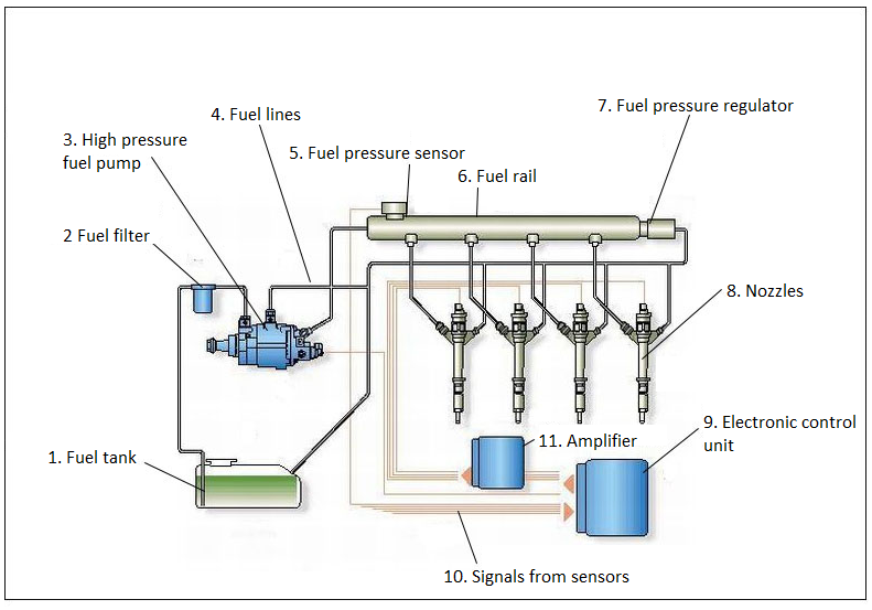
Structurally, the Common Rail system is divided into low and high pressure circuits and consists of the following elements:
- Pumping fuel pump. It supplies diesel fuel from the tank to the pressure line.
- The fuel filter is equipped with a valve for preliminary heating at low temperatures.
- Auxiliary fuel pump. Performs fuel pumping from the injection line.
- Mesh filter.
- Temperature sensor. Fixes the fuel heating level in the system.
- TNVD (high-pressure fuel pump) - the distribution type pump is most often used.
- Dosing valve. It regulates the amount of fuel entering the ramp.
- Diesel pressure regulator. It is necessary to maintain the specified fuel pressure indicators in the high-pressure main.
- Fuel rail or battery. In fact, it is a tube, along the length of which there are fittings for attaching nozzles.
- Pressure sensor. Located in the high pressure main. It captures and transmits relevant data to the ECU (electronic control unit) of the engine.
- Reducing or bypass valve. Allows you to maintain the pressure indicator in the return line at the level of 1 MPa, which ensures the correct operation of the nozzles.
- Fuel injectors. There are two types: electro-hydraulic or piezoelectric. The first are controlled by an electromagnetic valve, and the second are equipped with piezo crystals, which allows you to significantly increase the speed of their work.

More than 70% of all produced diesel engines are equipped with Common Rail fuel systems.
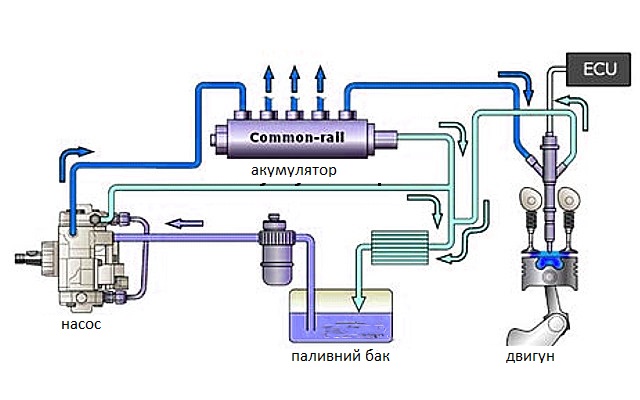
Features and principle of operation
The principle of operation of this type of fuel system is based on the distribution of the processes of creating high pressure and direct injection of diesel. From the fuel tank, fuel is pumped into the system by a low-pressure pump. At the same time, it passes through filters, where it is cleaned of impurities and various impurities. Through the low-pressure circuit, diesel fuel enters the high-pressure pump, which has a mechanical drive. He, in turn, injects fuel into the ramp, where it accumulates until the moment of injection. This allows you to constantly maintain the desired pressure level regardless of the current engine operating mode.
Receiving data from the sensors of the system, the engine ECU determines how much fuel the injection pump needs to supply to the fuel rail. After that, the fuel dosing valve entering the battery opens. At the same time, the fuel is under a given pressure level, which is maintained by the regulator.
As soon as the required volume of diesel is pumped into the ramp, the ECU sends a command to open the injectors that correspond to the engine's cycle. During one cycle of operation of such a system, multiple injection is carried out, consisting of three stages:
- The previous one is the necessary increase in temperature and compression in the combustion chamber, which allows you to accelerate the ignition process. At idle, two pre-injections can be performed, when revs increase - one, and at full power there is no pre-injection.
- The main one - directly ensures the operation of the engine.
- Additional - necessary to increase the heating temperature of exhaust gases, which ensures the combustion of soot and the reduction of harmful emissions into the atmosphere.
Advantages and disadvantages of the Common rail system
Initially, the level of pressure created at the fuel ramp was 140 MPa. Starting with the fourth generation, the system made it possible to reach indicators up to 220 MPa. Such progress made it possible to achieve an increase in the amount of fuel injected into the engine cylinders in one cycle, and therefore to increase the power of diesel cars.
Accumulator fuel systems use a whole set of sensors that allow you to take into account:
- pressure in the main pipeline;
- crankshaft rotation speed;
- air consumption, gas pedal position;
- fuel and air temperature;
- lambda probe data.
The signals coming from these sensors allow the ECU to optimize the operation of the diesel engine as much as possible. Compared to injection pump systems, the maintainability of Common Rail is higher than a simpler device.
Among the disadvantages of the Common Rail system is the need to use higher quality fuel. Since in such engines structurally complex injectors are used, their resource is lower. It is also very important to ensure complete tightness. So, for example, if the injector breaks, its valve will always be in the open position, and the fuel system will stop working.
The appearance of the Common Rail fuel system was a real breakthrough in the production of diesel engines. It enabled the application of high environmental standards for diesel engines of all classes, which are actively being implemented in developed countries.
Common rail injectors
Common rail injectors, which began to be installed on foreign diesel cars since the 90s of the last century, were later replaced by simpler mechanical diesel injectors that are activated by fuel pressure. And now under the hood of almost any foreign diesel car (except older cars) nozzles of this type are installed. This article will describe in detail the principle of operation and arrangement of modern diesel injectors of the common rail system, what they are and other nuances.

First of all, it should be said that the engineers of many automotive countries began to develop injectors of this type back in the 70s, and quite successful work was also carried out in the Soviet Union. But the first industrial samples, which were put on the market around 1997, were developed by the Robert Bosch company, and together with the GmbH, Elasis and Fiat companies.
To be precise, there are two main types of common rail diesel injectors: electro-hydraulic and piezo-electric. Both types are used on modern diesels and both types of injectors will be described in detail below.
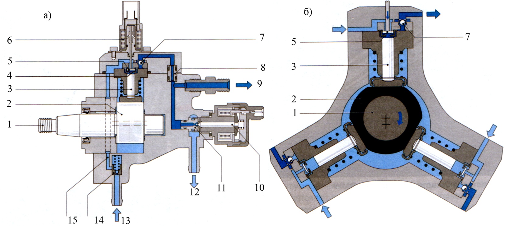
The device and principle of operation of the common rail injector
From the fuel ramp (rail), diesel fuel enters the nozzle through the high-pressure pipeline through the inlet fitting 4. Then, through the channel 10 and the nozzle 7, the fuel enters the so-called hydraulic control chamber 8. This chamber is connected to the return line through the nozzle 6, which opens and closes with the help of a solenoid valve.
1 - electro-hydraulic nozzle. A - the nozzle is closed, B - the nozzle is open (injection). 1 - return drain channel, 2 - terminal (electrical connector), 3 - electromagnetic valve (solenoid), 4 - inlet channel (high-pressure pipeline fitting), 5 - ball valve, 6 - jet, 7 - inlet channel jet, 8 - hydraulic chamber 9 - plunger, 10 - fuel channel, 11 - injector shut-off needle.
If the nozzle 6 is blocked, then the force of fuel pressure that affects the plunger 9 is much greater than the force of pressure applied to the cone in the middle part of the locking needle 11 (the pressure presses on the needle from below and tends to raise it, but this pressure is still less than the pressure that affects the plunger 9 and needle 11 from above). Because of this, the closing cone of the needle is quite tightly pressed to its seat and reliably blocks the flow of fuel, which is under high pressure, into the combustion chamber of the engine.
But when an electric signal is applied to the control solenoid of the electric valve, the nozzle 6 immediately opens, while the pressure in the hydraulic control chamber instantly decreases and the force of fuel pressure pressing on the plunger 9 from above also decreases. And now the pressure force acting on the plunger 9 from above becomes less than the fuel pressure force acting on the locking needle from below.
At the same time, the force of pressure acting on the locking needle from below also overcomes the resistance of the spring, which is indicated by the red arrow in Figure 1 a. And so, at this moment, the cone of the needle separates from its seat and fuel is injected into the combustion chamber of the engine.
The above-described effect on the closing needle of the injector, with the help of a pressure difference (the so-called multiplier system, which works with the help of a controlling fuel dose), allows you to instantly affect the needle, very quickly separating the cone of the needle from its seat, to cause fuel injection, which it would be impossible to do with the direct effect of the electric valve on the needle (the solenoid of the electric valve is activated much more slowly).
At the same time, the so-called control dose of fuel, with the help of which the needle opens instantly, is not injected into the combustion chamber, but goes back, through the nozzle 6 of the hydraulic control chamber, into the return pipeline (indicated by the white arrow) and further into the fuel tank.
Now I will briefly describe the operation of the common rail injector in the process of four stages of its operation:
- The initial state, when the nozzle is closed with added high pressure from the ramp, is the first stage of operation.
- Then the second stage, when the nozzle opens and the injection begins.
- The third stage, when the nozzle is fully open (the shut-off needle is raised above the nozzle holes).
- And the fourth stage, when the cone of the locking needle sits in its place in the seat and the needle covers the holes of the atomizer, that is, the nozzle closes (end of injection).
These four operating stages are the result of pressure forces applied to the internal parts of the nozzle.
And now all these 4 stages in more detail, during the operation of the nozzle:
In the initial state, the nozzle is closed (see figure A), that is, its closing cone is tightly pressed to its seat, also with the help of a spring, and blocks the flow of fuel into the combustion chamber (of course, injection is impossible). At the same time, diesel fuel from the fuel ramp through the high-pressure pipeline at a pressure of at least 300 kg/cm² enters through the inlet fitting 4 and the cavity indicated by the black arrow inside the nozzle.
At a certain desired moment of fuel injection, a voltage pulse is sent from the ECU to solenoid 3, at the same time the electromagnetic valve opens (see figure B), the ball 5 also rises above the outlet opening and opens the fuel outlet, and the fuel also begins to drain into the return ( by the white arrow in the picture).
As a result, the fuel pressure in the control chamber decreases, and the fuel pressure pressing on the needle from below increases and, overcoming the force of the spring, the pressure lifts the needle, tearing its cone from the injector seat and opening the nozzle hole for fuel injection into the combustion chamber of the diesel engine, under a pressure of almost equal to the pressure in the fuel rail (ramp).
As soon as the ECU disconnects the control voltage from terminal 2 of the solenoid of the electric valve, it immediately closes and the pressure in the control chamber immediately increases, from the pressure created in the ramp and enters the nozzle through the high-pressure pipeline, and internal pressure is created again, which presses on the plunger 9 from above through the nozzle 7.

And accordingly, the plunger presses on the needle from above, and together with the spring tightly presses the locking cone of the needle to its seat, covering the opening of the sprayer. And then everything repeats itself, when the ECU again, at the right moment, will supply the controlling voltage (pulse) to terminal 2 of the injector solenoid valve. If there is no internal pressure inside the nozzle, the needle closes the nozzle hole only due to the effect of the closing spring (indicated by the red arrow in the figure).
Repair and availability of spare parts for electro-hydraulic injectors is much easier than the repair of piezo injectors, which will be described below. And the technical capabilities of many specialized centers in large cities make it possible to restore almost all electro-hydraulic injectors from the well-known company "Bosch", it is a little more difficult with spare parts for the company "Delphi" (new injector bodies, nozzles, shut-off valves, solenoid coils are sometimes very difficult to find. for this company, but in big cities or via the Internet, everything is now possible).
Well, it is impossible to find original spare parts for injectors of the Japanese company "Denso" (although the Internet is gradually improving the situation), well, unless there are fakes from some Asian company. It is not known how many such spare parts will be processed. The cost of repairs naturally depends on the region where the service station is located, as well as on the number of parts to be replaced, as well as on the manufacturer of these parts and the injector itself. And it is clear that the more worn parts are replaced, the more expensive it is to repair the injector, so I will not give the exact figure.
The ceiling for repairing Bosch injectors is approximately one hundred and fifty dollars, and the maximum cost of repairing "Denso" or "Delphi" injectors will cost approximately one hundred dollars more (in most cases, non-original spare parts will be installed on "Denso").
But the principle of operation of piezo-injectors is also based on the hydraulic system, that is, from the action of bleeding and reducing the fuel pressure above the shut-off needle, but more on this below. When electrical voltage is not applied to the terminal 12 of the piezo injector, the locking needle with its cone blocks the nozzle holes due to the high fuel pressure acting on the piston (as well as from the effect of the locking spring 3, which presses on the needle even when there is no fuel pressure in system).
When it is necessary to inject fuel, at the right moment, voltage is supplied from the ECU to terminal 12 of piezo element 9, which increases the length of the piezo crystal and starts to press on the piston of the pusher 8, which in turn presses and opens the switching valve 5, and through this already open valve, diesel fuel begins to flow into the return fuel line.
At the same time, the fuel pressure pressing on the locking needle 1 from above is noticeably reduced, and due to this, the fuel pressure pressing on the needle from below is able to raise the needle and open the nozzle holes for injection. Moreover, the amount of diesel fuel injected into the combustion chamber depends on the duration of the voltage effect on the piezoelectric element of the nozzle (the duration is determined by the ECU), and also depends on the pressure created in the fuel rail (ramp) of the fuel system of a modern diesel engine.
The advantages of piezo injectors were described above, and their main disadvantage is that their complete repair is unrealistic (especially injectors from the companies "Denso", "Bosch" and the company "Delphi"). With electrohydraulic injectors of these companies and spare parts for them, it is much easier than with piezo injectors. A little easier with spare parts for some piezo injectors from Siemens (now Continental).
You can of course partially restore their performance and eliminate the consequences of our terrible fuel by removing the tips and washing them on an ultrasonic stand. And then check the operation of the injectors on a special diagnostic stand, if you take them to a specialized center.
We considered both types of common rail injectors, their device and principle of operation, as well as the main pros and cons of each type of injector. And now let's go in more detail to their manufacturers, which were described a little above.
Value
the code is triggered by the engine control module when the code is stored in the transmission control module
Possible reasons
- Defective gearbox control module;
- Wiring harness of the transmission control module is broken or shorted;
- The electrical circuit of the transmission control module has a faulty connection.
P0704 : Clutch switch input circuit malfunction
Value
When the clutch pedal is depressed, the voltage signal from the clutch switch to the engine control module is low. If the ECM does not see this change from high to low when the vehicle speed is above 0 mph, it will set code P0704.
When is the code revealed?
The ECM did not detect any movement in the clutch pedal position switch
Technical notes
Check the clutch switch adjustment, the switch should open and close when the clutch pedal is depressed. If the switch is properly adjusted, replace the clutch switch to fix the problem.
Possible reasons
- Malfunction of the clutch switch;
- Incorrectly adjusted clutch switch;
- The wiring harness of the clutch switch is broken or shorted;
- Clutch switch circuit poor electrical connection;
- Faulty engine control module.
P0705 : Transmission range sensor circuit malfunction
Value
The park/neutral switch includes a transmission range switch. The transmission range switch detects the position of the selector lever when the shift lever is in the N or P position and sends a signal to the transmission control module.
When is the code revealed?
The range switch of the box detects the position of the selector lever and sends a signal to the TCM.
Possible reasons
- Malfunction of the parking/neutral switch;
- Improper adjustment of the parking/neutral switch;
- Break or short circuit in the wiring harness of the parking/neutral position switch;
- Poor electrical connection in park/neutral switch circuit.
FUEL SYSTEM: COMPONENTS, OPERATING PRINCIPLES, SYMPTOMS AND EMISSION CONTROL
The function of the fuel system is to store and deliver fuel to the cylinder chamber where it can mix with air, vaporize and burn to produce energy. The fuel, which can be gasoline or diesel, is stored in the fuel tank. The fuel pump sucks fuel from the tank through the fuel lines and feeds it through the fuel filter or carburetor or fuel injector, and then delivers it to the cylinder chamber for combustion.

Components
1. Fuel tank.
The fuel tank is the main storage of fuel that drives the car. Generally speaking, the gas tank is usually located in or under the rear of the vehicle.
2. Fuel injectors.
Sprays a fine mist of fuel into the combustion chamber of each cylinder or throttle body, depending on design.
The fuel injectors are actuated by the fuel pump, and their job is to spray a fuel-air mixture into the combustion chamber, ready for ignition to generate power to the driven wheels. and air droplets (spray). Basically, it can be thought of as a perfume sprayer or deodorant that sprays a fine mist.
3. Fuel filling hose.
The fuel filler hose is the main connector that connects the gas cap to the tank. This is the point at which gasoline (or other fuel) is poured into the car.
4. Gas cap.
The gas cap closes the fuel hose and is used to ensure that
A) Gas does not spill out of the car;
B) the fuel system remains under the correct pressure (in vehicles that use pressurized systems).
5. Fuel pump.
The fuel pump is used to pump fuel from the fuel tank through the fuel lines to the fuel injectors, which spray the fuel into the combustion chamber to cause combustion. There are two types: mechanical fuel pumps (used in carburetors) and electronic fuel pumps (used in electronic fuel injection).
• Mechanical fuel pumps: These are usually used by additional belts or chains from the engine.
• Electronic Fuel Pumps: Controlled by an electronic fuel injection system, these are generally more reliable and have fewer reliability issues than their mechanical counterparts.
6. Fuel filter.
The fuel filter is the key to the proper operation of the fuel supply system. This is more correct for fuel injection than carbureted cars. Fuel injectors are more prone to dirt damage due to their tight tolerances, but fuel-injected vehicles also use electric fuel pumps. When the filter becomes clogged, the electric fuel pump works with such force to push through the filter that it burns. Most cars use two filters. One inside the gas tank and one on the line of fuel injectors or carburetor. Unless there are some serious and unusual conditions that cause a large amount of dirt to enter the gas tank, it is only necessary to replace the filter in the pipeline.
7. Fuel lines.
Fuel lines connect all the different components of the fuel system.
Steel piping and flexible hoses carry the fuel from the tank to the engine. Do not use copper or aluminum when servicing or replacing steel piping. Steel lines must be replaced with steel ones. When replacing flexible rubber hoses, the appropriate hose must be used. Ordinary rubber, such as that used in vacuum or water hoses, softens and deteriorates. Be careful to route all hoses away from the exhaust system.
8. Fuel level indicator.
The fuel gauge exists as a display element on the car's instrument panel. It is designed to show the driver the actual amount of fuel in the fuel tank. On older cars, fuel level sensors (or the related part that transmits the unit) are usually inaccurate. When you first start driving your classic car, take the time to learn how accurate this system is. This will save you a long walk to the gas station if you run out of gas!
9. Fuel level indicator sending node.
As far as the fuel system goes, this can be your biggest headache. Sending blocks are poorly designed at best. As a rule, the most accurate sender gives from 1/4 to 3/4 of a gas cylinder. In addition, the sensor becomes increasingly inaccurate as you reach the limits of the tank (full or empty).
Depending on the age of the vehicle, the type of carburettor / fuel injection and the emission standards in effect at the time, there may also be:
10. Fuel return pipelines.
These are usually the same types of pipelines as the main fuel line. These particular strings are used for several purposes. They are primarily used to return excess fuel to the gas tank for recirculation. In addition, they capture gasoline vapors, which, falling back into the gas tank, cool and condense again into a liquid. In particular, fuel-injected diesel engines often use fuel as a cooling mechanism for the fuel injector. They can recirculate a significant amount of fuel.

11. Control of vapor emissions.
Often used in conjunction with fuel return lines. The purpose of this part of the entire system is to ensure that gasoline vapors do not enter the surrounding air. If this happens, a number of unpleasant things can happen: 1) A huge emission of gasoline vapors, 2) The unpleasant smell of gasoline enters the car, and 3) It can harm the environment.
12. Fuel pressure regulator.
Fuel pressure regulators
mainly used in cars with a fuel injection system. Fuel injection, unlike carburetion, is a high-pressure system. The fuel pressure regulator ensures proper pressure is maintained in the system.
13. Pulsation damper.
As the fuel injectors open and close rapidly in accordance with the engine's OTTO cycle, pressure fluctuations occur in the fuel system. The job of a pulsation damper is to help combat pressure levels by reducing fuel delivery variability.
WORKING PRINCIPLE
Some of this may sound a little silly, as many of the components are pretty obvious to all of us. In fact, as soon as you fill the gas tank, the system is "ready". When you start your car, the fuel pump starts the process of sending fuel from the fuel tank through the fuel lines and fuel filter to the system that controls the fuel/air supply to the engine (carburetor or fuel injector). This provides a continuous supply of fuel while the vehicle is moving.
The fuel system of modern cars is a complex and intricate combination of components and electronics. Typically, fuel systems work as follows:
• Fuel is supplied from the fuel tank to the fuel injectors via the fuel pump and fuel lines. The pump is usually located next to the fuel tank or inside the tank.
• Fuel leaving the fuel tank and fuel pump passes through a fuel filter that cleans and removes any contaminants. Typically, this is a linear design with high throughput to maximize throughput.
• Fuel passes through the fuel lines and enters the fuel injectors. The pressure in the fuel injector is regulated using a pressure regulator.
• Any unused fuel that exceeds the allowable pressure is returned through the fuel lines back to the fuel tank.
Carburetor engines
The fuel system for this type of engine is usually a low pressure system. If the vehicle is equipped with a mechanical fuel pump, the number of engine revolutions (rpm) determines the fuel delivery rate. The faster the car moves (or revs), the harder the fuel pump works and the total amount of fuel delivered. If the vehicle is equipped with an electric fuel pump, the general process is the same, but a restrictor of some form must be installed to ensure that the required amount of fuel is supplied. This can be a pressure regulator, an overflow system with return lines, or a vehicle-specific mechanism.

Engines with fuel injection
After starting the engine, provided that the gas cap has been installed and sealed correctly, the system is pressurized. Your modern car is probably fuel injected. Have you ever noticed air coming out when you go to fill up with gas? This is a car that releases pressure in the system. The electric fuel pump continuously pumps gasoline, providing the necessary level of pressure in the system. In addition to the normal fuel supply, it also passes through a pressure regulator, which ensures the correct fuel pressure at the injector point, so that the amount of fuel injected into the engine is appropriate. Depending on the year of manufacture and the vehicle in question, the level of technology controlling the system can be a simple wiring type control or a computer.
SYMPTOMS
The main symptoms of any type of vehicle fuel system showing signs of wear or tear are:
• Difficulty starting the engine
• Slow or uncertain acceleration
• Mud while driving
• Periodic loss of power
• Check Engine or Service Light Engine Soon light is on
• The engine does not idle
• Excessive engine smoke
• Perceptible smell of fuel
• Reduced fuel economy
EMISSION CONTROL
Emission controls are an addition to the base fuel system and vary in complexity depending on the year of manufacture, vehicle and legal measures in place at the time of manufacture. from the system. Because of the variability in this particular segment of the system, it is important that you familiarize yourself with the technical information that is specific to your vehicle.
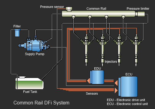
Common Rail injection system
CRDI - Common Rail Injection System
Common Rail direct fuel injection is a modern version of the direct fuel injection system for gasoline and diesel engines. from the low-pressure fuel pump of the nozzle of the supply unit (or nozzle). Third-generation Common Rail diesels now feature piezoelectric injectors for increased precision with fuel pressures up to 3,000 bar (300 MPa; 44,000 psi). In gasoline engines, this is used in direct injection gasoline engines.
Principle of operation
Electromagnetic or piezoelectric valves allow precise electronics to control the timing and amount of fuel injection, as well as the higher pressure that Common Rail technology provides for better fuel atomization. For low engine noise, the electronic engine control unit can inject a small amount of diesel fuel immediately before the main injection ("pilot" injection), thereby reducing its explosiveness and vibration, as well as optimizing the injection time and quantity to change fuel quality, cold start and so on. Some advanced common rail fuel systems perform up to five injections per stroke. Common rail engines require a very short (<10 seconds) warm-up time [ depending on ambient temperature and produce lower engine noise and emissions compared to older systems used various forms of fuel injection. Two common types include block injection systems and distributor/in-line systems pump (see diesel engine and unit injector for more information). Although these older systems provided precise control of fuel quantity and injection timing, they were limited by several factors:
- They were cam-driven, and the injection pressure was proportional to engine speed. This usually meant that the highest injection pressure could only be achieved at the highest engine speed and the maximum achievable injection pressure decreased as the engine speed decreased. In block or distribution systems, the injection pressure depends on the instantaneous pressure of a single pumping event without an accumulator, and thus the relationship is more pronounced and problematic.
- They were limited in the number and timing of injection events that could be controlled during a single combustion event.
- For a typical distribution/line system, injection would start at a set pressure (often referred to as: pop pressure) and end at a set pressure. This characteristic resulted from "dummy" nozzles in the cylinder head, which opens and closes at pressures determined by the pretension of the spring applied to the plunger in the injector. As soon as the pressure in the nozzle reaches the set level, the piston will rise and injection will begin.
In common rail systems, the high pressure pump accumulates a reservoir of fuel at high pressure - up to and above 2,000 bar (200 MPa; 29,000 psi). The term "common rail" refers to the fact that all fuel injectors are fed from a common fuel rail, which is nothing more than a pressure accumulator in which fuel is stored at high pressure.
This battery powers multiple fuel injectors from high pressure fuel. This simplifies the purpose of the high pressure pump, where it only needs to maintain a set pressure on the target (either mechanically or electronically controlled). Fuel injectors are usually controlled by the ECU. When the fuel injectors are electrically activated, a hydraulic valve (consisting of a nozzle and a plunger) is mechanically or hydraulically opened and fuel is sprayed into the cylinders at the desired pressure.

Since the energy of the fuel pressure is stored remotely and the injectors are electrically driven, the injection pressure at start and end of injection is very close to the pressure in the accumulator (ramp), therefore producing a quadratic injection rate. If the accumulator, pump and piping are correctly selected, the pressure and injection rate will be the same for each of the multiple injection events.
annotation
Productivity and efficiency of a diesel engine
continue to improve, but as engine exhaust regulations become more stringent, there is a need for more sophisticated control of the combustion cycle. Emission standards limit the amount of NOx, soot and CO produced during engine combustion. To cope with the emission reduction requirements, diesel engines are now being designed using Common Rail injection system which provides the best atomization of the air-fuel mixture resulting in increased engine efficiency. cylinder temperature control, which will lead to a decrease in harmful emissions, as well as a decrease in engine noise.

To provide better emission and efficiency control, the Renewable Energy Lab will focus on converting the mechanically fuel injected engine to a common rail system. The system will be controlled by a stand-alone data acquisition and I/O unit, which will allow virtually unlimited control over system parameters, giving future researchers the opportunity to design the system according to their specific field of research. The data acquisition unit and drivers use the Lab-View architecture and allow simultaneous control of both direct injection and port fuel injection systems. It also uses control loop feedback principles to adjust fuel rail pressure, helping to obtain accurate and repeatable data.
Common Rail systems allow for the best control of the injection cycle of an internal combustion engine by using high pressure fuel, injectors with extremely short response times and precise control of fuel flow throughout the engine's operating range. All these attributes are possible because Common Rail uses a high-tech injector that works on the principle of piezoelectricity, when mechanical stress produces an electrical charge. The principle also works in reverse. The injector contains a piezo-sensitive material, and short bursts of electrical current cause the material to contract and expand, opening the injector. Because the system is electronically controlled, it can open and close the injector up to eight times during an injection cycle and change the opening and closing times for each event. This is far beyond what a mechanically injected system can do, and it is for this reason that common rail diesel systems are far superior to mechanically injected internal combustion engines in terms of efficiency.
Diesel engine performance and efficiency continue to improve, but as engine exhaust regulations tighten, there is a need for more sophisticated control of the combustion cycle. Emission standards limit the amount of NOx, soot and CO produced during engine combustion. To cope with the emission reduction requirements, diesel engines are now being designed using Common Rail injection system which provides the best atomization of the air-fuel mixture resulting in increased engine efficiency. The Common Rail system also better controls ignition advance and can use multiple injection events to control cylinder temperatures, resulting in lower emissions as well as lower engine noise.
To provide better emission and efficiency control, the Renewable Energy Lab will focus on converting the mechanically fuel injected engine to a common rail system. The system will be controlled by a stand-alone data acquisition and I/O unit, which will allow virtually unlimited control over system parameters, giving future researchers the opportunity to design the system according to their specific field of research. The data acquisition unit and drivers use the Lab-View architecture and allow simultaneous control of both direct injection and port fuel injection systems. data.
Common Rail systems enable the best possible control of the injection cycle of an internal combustion engine by using high-pressure fuel, injectors with extremely short response times and precise control of fuel flow throughout the engine's operating range. All these attributes are possible because Common Rail uses a high-tech injector that works on the principle of piezoelectricity, when mechanical stress produces an electrical charge. The principle also works in reverse. The injector contains a piezo-sensitive material, and short bursts of electrical current cause the material to contract and expand, opening the injector. Because the system is electronically controlled, it can open and close the injector up to eight times during an injection cycle and vary the opening and closing times for each event. This is far beyond what a mechanically injected system can do, and it is for this reason that common rail diesel systems are far superior to mechanically injected internal combustion engines in terms of efficiency.